Behavior of the Shock Wave Propagating in the Small Diameter Tubes
Shinsuke Udagawa
1
Walter Garen
2
Tatsuro Inage
3
Masanori Ota
4
Kazuo Maeno
51Aerospace Engineering Course, Tokyo Metropolitan College of Industrial Technology
2Department of Photonics, University of Applied Science Emden/Leer
3Department of Mechanical and Electronic Engineering, Salesian Polytechnic
4Graduate School of Engineering, Chiba University
5President, Kisarazu National College of Technology
In our previous research, we developed a diaphragmless driver section with two pistons for a small diameter shock tube based on the technique which was invented and applied by Oguchi, et al.[1] and Maeno, et al.[2, 3]. Additionally, by using the laser differential interferometer, we measured the shock wave, which is propagating in the small diameter tubes, generated by the diaphragmless driver section that we developed. According to our experimental results, the longer shock wave forming distance occurred by the slower actuation of the main piston, which is one of the components that constitute the diaphragmless driver section, at the initial opening process [4-6]. Therefore, we improved the main piston to achieve the faster actuation of the main piston especially at the initial opening process. Consequently, the opening time of the main piston was achieved about 85% reduction by the improvement of the structure for the main piston [7, 8].
In this study, we have measured the shock wave, which is generated by the diaphragmless driver section with the improved main piston, propagating in the small diameter tubes. Figure 1 shows the schematic drawing of the diaphragmless driver section with the improved main piston named a UMO (Udagawa-Maeno-Oguchi) valve [7]. The unique modification point from MO valve is the replacement of the main piston [4-6]. The improved main piston consists of a free piston with a magnet and a housing made of Ti based alloy. The housing, which is perforated for the gas vent holes, and the magnet settled inside the free piston are to prevent the unintended actuation of the free piston which is induced by the resistance between the free piston and the housing. The aim of this improvement is to achieve the faster opening time by the impulse transfers from the housing to the free piston, especially at the initial opening process. Firstly, the housing actuates at the initial opening process. The free piston is actuated by the collision, which is occurred after that the housing moves the backlash x between the housing and the free piston.
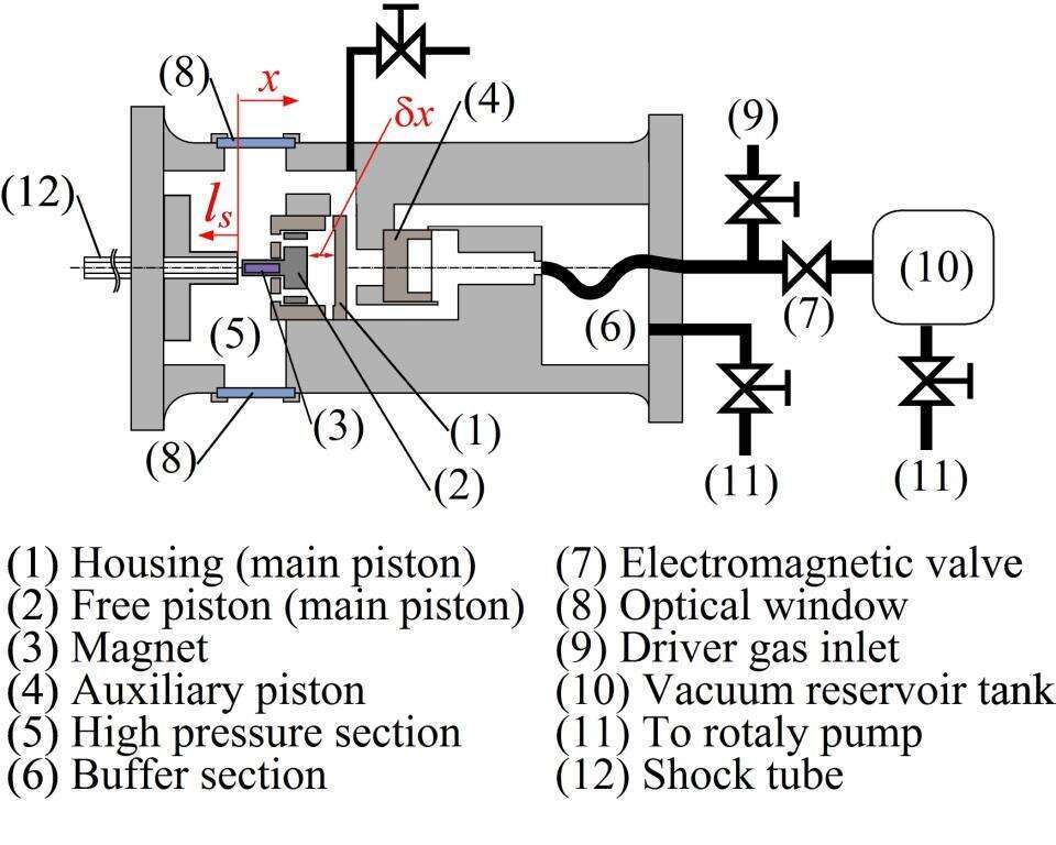
Figure 1. Schematic drawing of the diaphragmless driver section with improved main piston
Figure 2 shows a schematic drawing of the measurement system used in this study. The glass tube, which is connected to the high pressure section, has the length l = 1000 mm. The position of the laser differential interferometer ls can be changed from 200 to 800 mm. The inner diameter of the tube d is used as 2 and 3 mm in this experiment. The pressure transducer is settled at the end of the tube to detect the reflected shock wave. The signals obtained from the interferometer and the pressure transducer are recorded to an oscilloscope. The shock wave propagation characteristics can be obtained from the time difference of the shock wave detections between the interferometer and the pressure transducer. The initial pressure ratio p4/p1 is maintained constant as 9 at the driven pressure p1 fixed 0.1 MPa. The driver and driven gases are helium and air respectively.
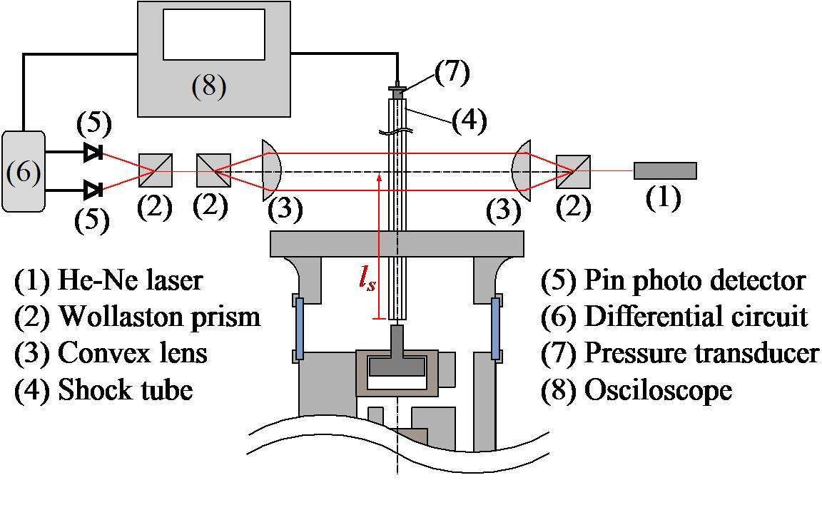
Figure 2. Schematic drawing of the measurement system
Figure 3 shows the relation between the Mach number of the shock wave and the measurement position along the shock tube. The horizontal and the vertical axes are the measurement position ls and the Mach number of the shock wave Ms, respectively. The dashed line and the dots represent the theoretical data obtained from the Rankine-Hugoniot relation and the experimental data obtained by changing the inner diameter d, respectively. The experimental results show that the Mach number of the shock wave Ms decreases with decreasing the inner diameter of the shock tube d. It is considered that the expansion waves interacting with the shock wave becomes relatively stronger caused by increasing the surface area per unit volume of the hot flow region behind the shock wave in case of the sufficiently small diameter of the shock tube. Additionally, it is shown that the experimental results exceed the theoretical data at the range from ls = 120 to 600 mm. It is considered that the extremely large cross sectional ratio A4/A1 produced the effect of shock wave acceleration.
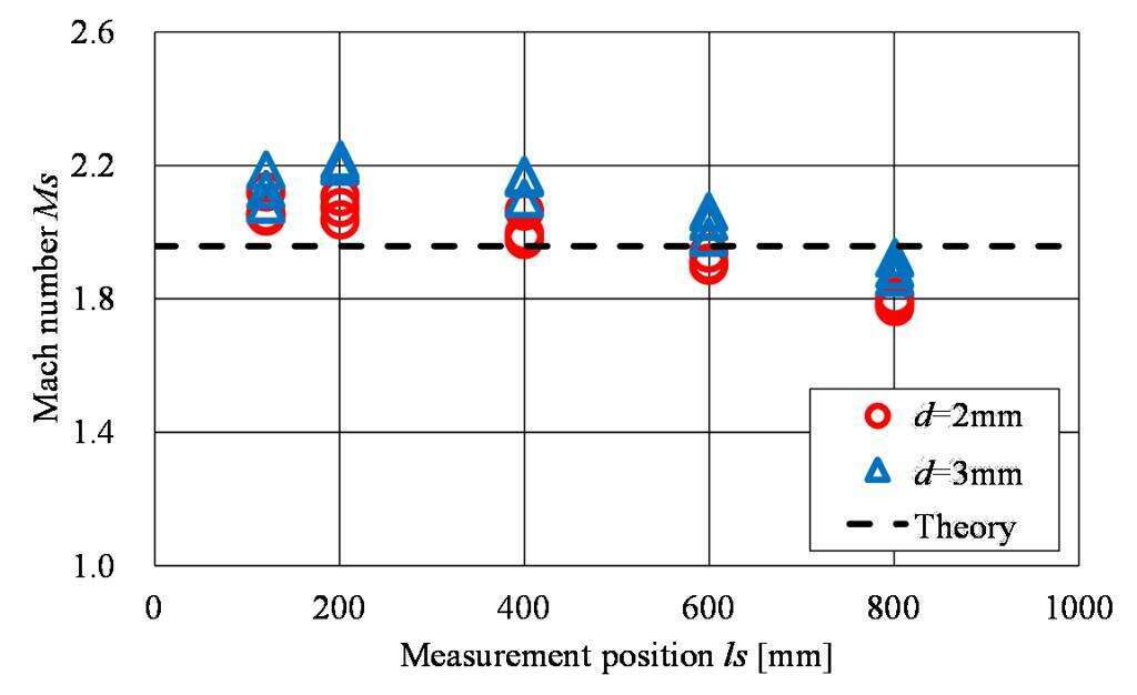
Figure 3. Relation between the shock wave Mach number and the measurement position along the tube
Acknowledgements This work was supported by JSPS Grant-in-Aid for Young Scientists (B) 26820051.
References
- Oguchi, H., et. al., Proc. of 10th Int. Shock Tube Sym., Kyoto, Japan, pp.386-391, (1975)
- Maeno, K. and Orikata, S., Proc. of 15th Int. Sym. on Shock Waves and Shock Tubes, Berkeley, California, pp.563-569, (1986)
- Maeno, K., et. al., Proc. of 16th Int. Sym. on Shock Waves and Shock Tubes, Aachen, Germany, pp.273-279, (1988)
- Udagawa, S., et. al., Transactions of the Japan Society of Mechanical Engineers B, vol. 78 (number 785), pp. 36-48, (2012) in JAPANESE
- Udagawa, S., et. al., Proc. of 28th Int. Sym. on ShockWaves, Manchester, United Kingdom, vol. 1, pp. 529-534, (2011)
- Udagawa, S., et. al., Kouku Uchu Gijutsu, vol. 11, pp. 99-105, (2012) in JAPANESE
- Udagawa, S., et. al., Proc. of 29th Int. Sym. on Shock Waves in USB Memory, Paper No.0246-000117, pp. 1-4, Madison, Wisconsin, USA, July, 2013.
- Udagawa, S., et. al., Proc. of the Sym. on Shock Waves in Japan in USB Memory, Presentation No.3C1-4, Aoyama Gakuin University, Kanagawa, Japan, March, 2014. in JAPANESE
|
