It will be interesting and important as well if there is a method that is capable of generating a shape/strength controllable shock wave. In this paper, we propose a new method to increase the intensity of a planar shock wave smoothly by means of specially designed wall contour along an area contraction channel. Based on a shock dynamics design method suggested by the author’s group1, a further development of a planar-to-planar shock wave enhancement was challenged recently, in which a smoothly concave-to-convex shaped convergent channel was designed for the control of the shock enhancement.


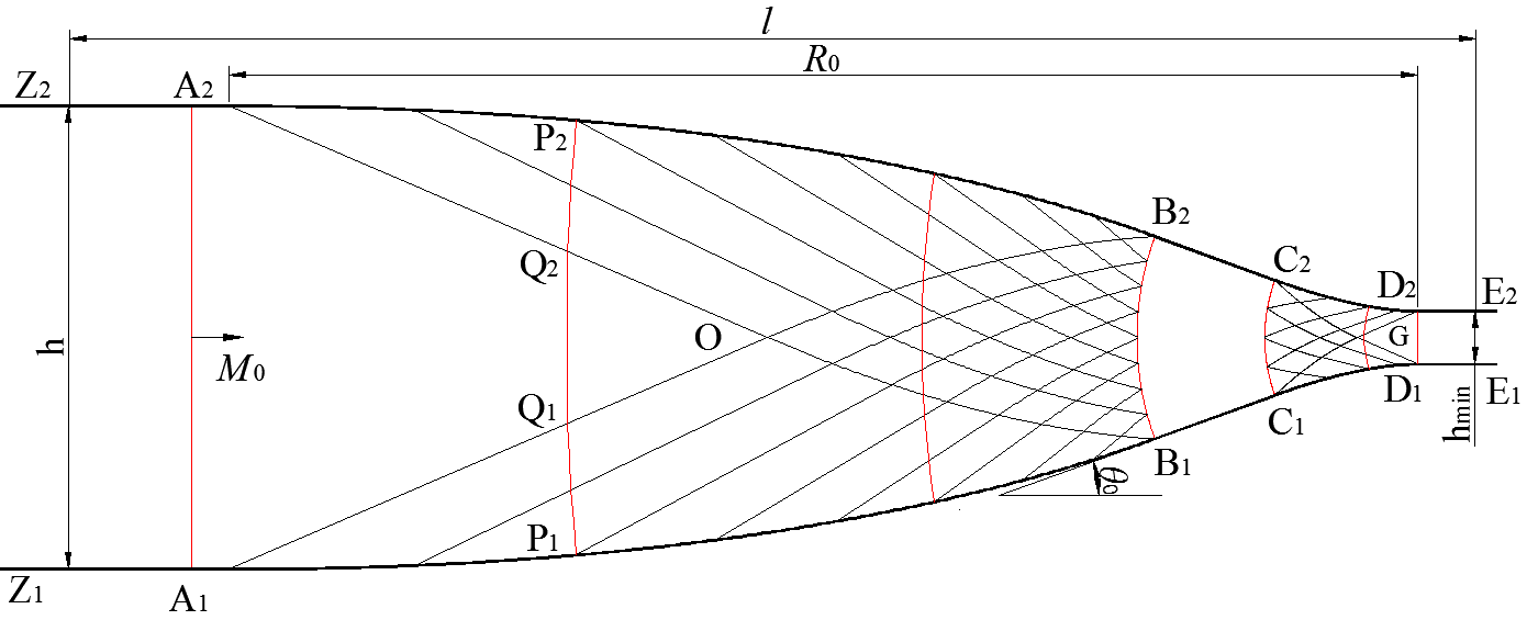
Fig.1 Schematic illustration of the design idea of the test section.
Fig. 1 shows the principle of a designed test section that “controls” the propagation of a shock wave. When a planar incoming shock wave encounters the contraction area, it is forced to transform into a cylindrical convergent one due to a continuous “shock compression” disturbance from the shock foot of the smooth concave walls (A1B1A2B2). The cylindrical shock front converges along the wedged contraction part (B1C1B2C2), where the contraction ratio is determined by the requirement of the shock enhancement. Once the curved cylindrical shock arrives at the downstream convex walls (C1D1C2D2), it is planarized again due to a continuous “shock-expansions” disturbance, whose effect is opposite to the former “shock-compression” disturbance, until all the previous disturbances are completely eliminated. Finally a strengthened planar shock wave is formed without disturbances at the exit of the convergent channel (D1D2).
A typical example is given here to verify the feasibility and reliability of the method. A shock tube with cross section of 40 mm X 70 mm, connected by a test section contracted from 70 mm to 8 mm and a converging angleθ0 =20o was tested for an incident shock Mach number Ms =3.2. The designed wall profile is examined through both numerical simulation and experiment. The numerical method used here was VAS2D (2-dimensional and axisymmetric vectorized adaptive solver), which has been well-validated in simulating compressible flows2. The experiment was visualized by a high-speed video camera (Phantom V710) combined with a conventional schlieren system, which was set to a frame rate of 100,000 fps (exposure time of 1μs) and spatial resolution of 384×152 pixels.

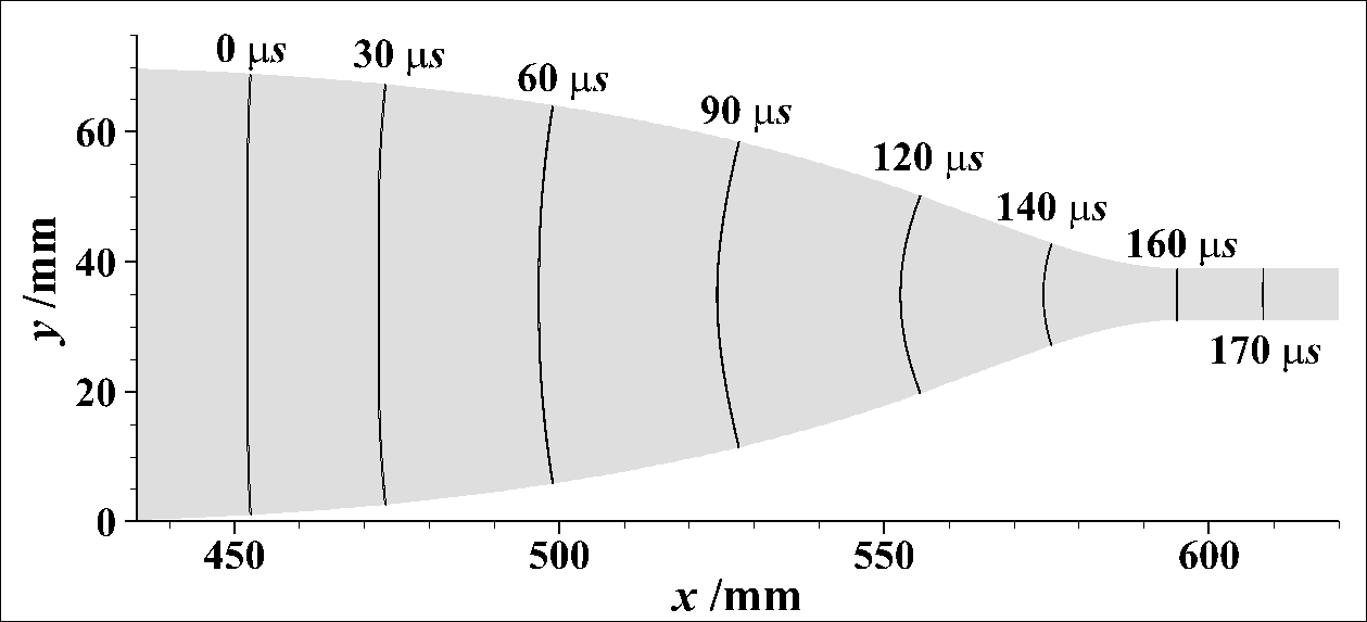
Fig. 2 Numerical schlieren at different times.

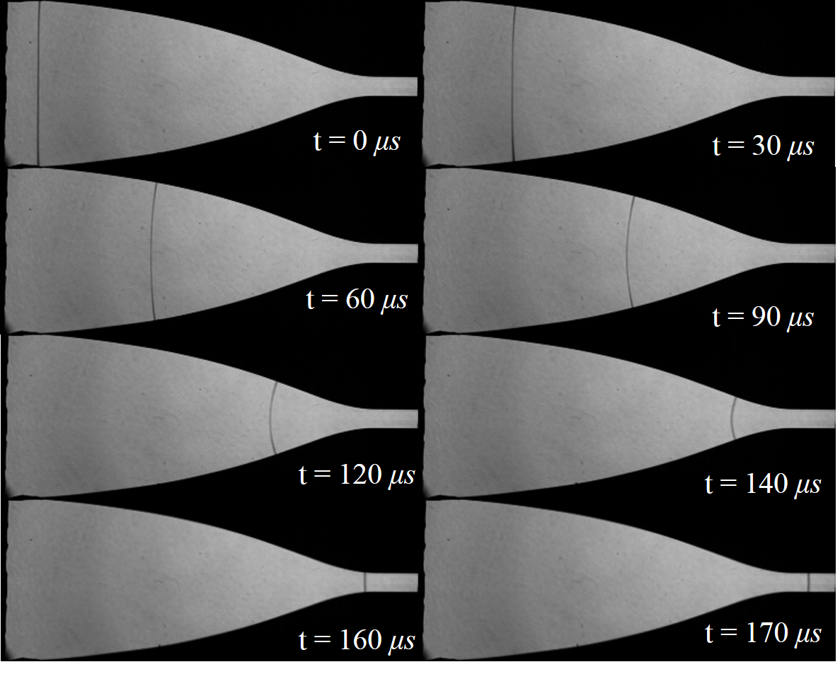
Fig.3 Experimental schlieren images at various time instants.
A series of numerical and experimental schlieren images showing the shock wave locations at different times are illustrated in Fig. 2 and Fig.3, respectively. It can be found that as the planar incoming shock travels into the smooth concave part of the test section, a gradual change starts from the shock foot near the wall, which spreads toward the center part of the shock front until a cylindrical shape is formed at the instant of about 120μs, where the wedged contraction part is located. The cylindrically shaped shock front continuously converge along this straight part of the wall (120-140μs), after which it enters the smooth convex part and gradually reduce the curvature (140-160μs). Finally, a strengthened planar shock wave is formed without obvious disturbance at the exit (160-170 μs), which gives the authors the confidence that the method works quite well and can be utilized for further research in the future.
Reference
- Zhai Zhigang, Liu Cangli, Qin Fenghua, YangJiming, Luo Xisheng. Generation of cylindrical converging shock waves based on shock dynamics theory[J]. Phy. Fluids, 2010, 22, 041701.
- Sun M, Takayama K. Conservative Smoothing on an Adaptive Quadrilateral Grid [J]. Journal of Computational Physics, 1999, 150(1): 143~180.

