I. Introduction
Modern trends in transonic aviation are connected with reducing of viscous drag. Therefore commercial airplanes of the next generations may be equipped with a laminar wing [1]. Generic feature of the transonic flow near the airfoil is presence of local supersonic zone ended by a shock wave. Laminar boundary layer has weak resistance to adverse pressure gradients especially ones produced by shock waves, in contrast to the turbulent boundary layer [2]. This leads to significant flow separation that can eliminate all advantages of laminar flow. Therefore it is necessary to estimate the difference between steady and unsteady parameters of the separation zone for various positions of the laminar-turbulent transition relative to the zone of shock wave boundary layer interaction (SWBLI) for moderate Mach numbers.
II. Experimental Setup
The experiments were performed in wind tunnel T-325 (ITAM SB RAS) for Mach number M∞ = 1.47, total temperature 291 K and four values of total pressure P0 = 0.55-1.0×10⁵ Pa. The configuration of the experimental model is presented in Figure 1(a). Experimental model consisted of a plate with sharp leading edge occupying full span of the test section and a wedge generating a shock wave. In this series of experiments, the wedge angle was 4º (regular reflection). The blockage ratio of the test section was relatively high therefore the flow start was provided by extended cavities above the wedge and below the plate. Variation of local boundary layer parameters and its state (laminar/turbulent) was provided by shifting of the flat plate in streamwise direction relatively to the wedge. To provide the same conditions near the leading edge the extension plates (length L) were installed downstream of the lower nozzle wall. The effect of natural laminar-turbulent transition on stationary and non-stationary parameters of the SWBLI was studied for three cases L = 100, 200 and 250 mm (Approximate distance from the leading edge to the intersection the incident shock wave with the model was equal to 285, 185 and 135 mm respectively). In the current study several types of roughness were considered (Fig. 1b). The main measurement techniques were PIV. Pitot tube was used to detect the position of the laminar-turbulent transition. These data revealed that extension plate of length L = 250 mm provided laminar inflow BL, L = 200 mm – transitional BL and L = 100 mm – turbulent BL.
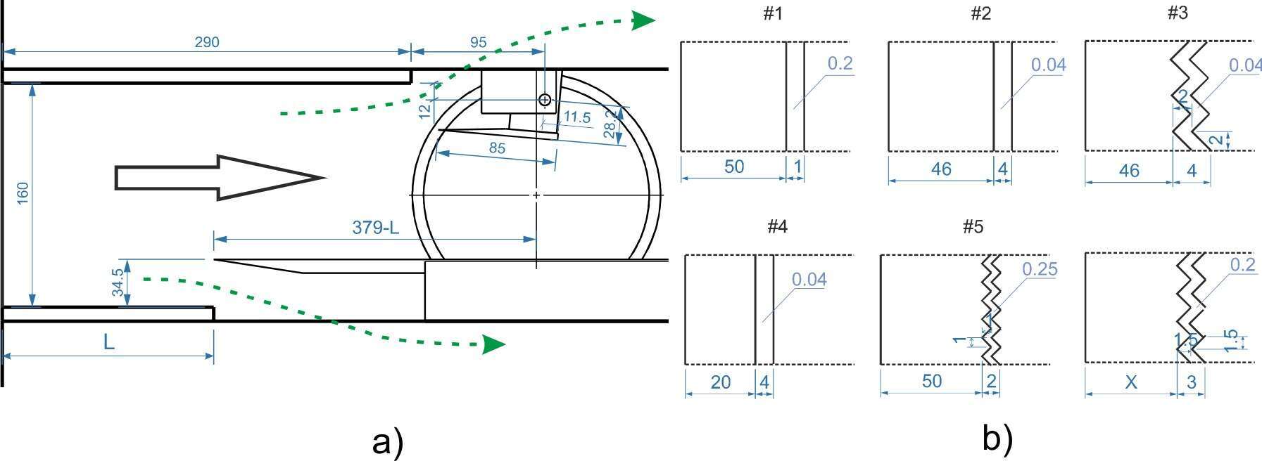
Fig. 1 The draft of a) experimental model and b) roughness
III. Experimental Results
Figure 2 presents the examples of the mean and pulsation flow in SWBLI for different states of the inflow boundary layer. It is clearly seen the significant difference of SWBLI. For the turbulent case small length of the interaction region isobtained, which leads to the generation of a strong reflected shock wave and Mach stem. For the case of laminar case the zone of interaction significantly increased, but it has less effect on the flow. Near the end of the interaction region a sharp increase of the boundary layer thickness comparable with the turbulent case is found. More significant difference in pulsations distributions pattern was found. For turbulent case the main growth of pulsations occurs near the reflected shock wave. Further downstream significant decrease of pulsations occurs. The maximum level of pulsations for the laminar case is much higher and occurs due to the laminar-turbulent transition.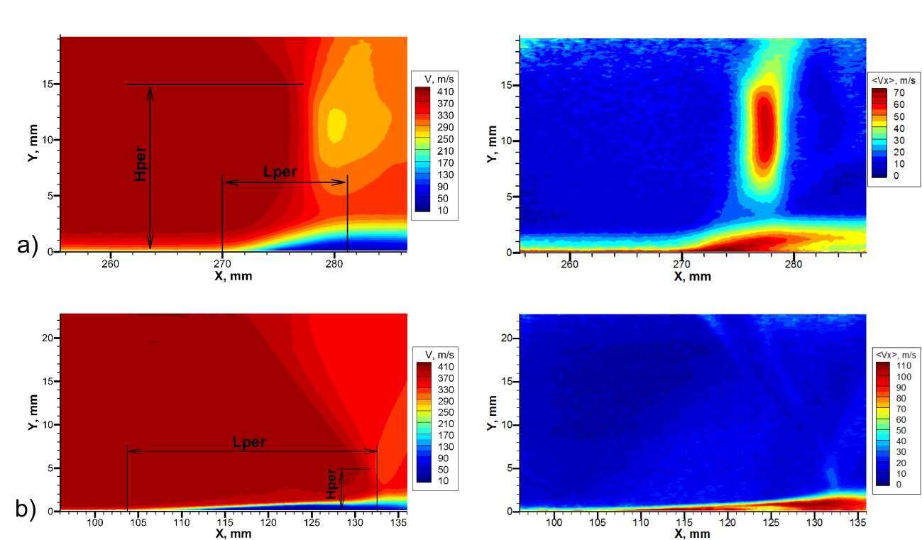
Fig. 2 Mean and RMS velocity fields for different inflow boundary layer: a) turbulent, b) laminar
It was decided to use the length (Lper) and height (Hper) of the interaction zone normalized by the displacement thickness of the inflow boundary layer to make comparative qualitative analysis (Fig. 3). Example of determining the length and height of the interaction zone can be found in fig.2 (more detailed description will be presented in the paper).
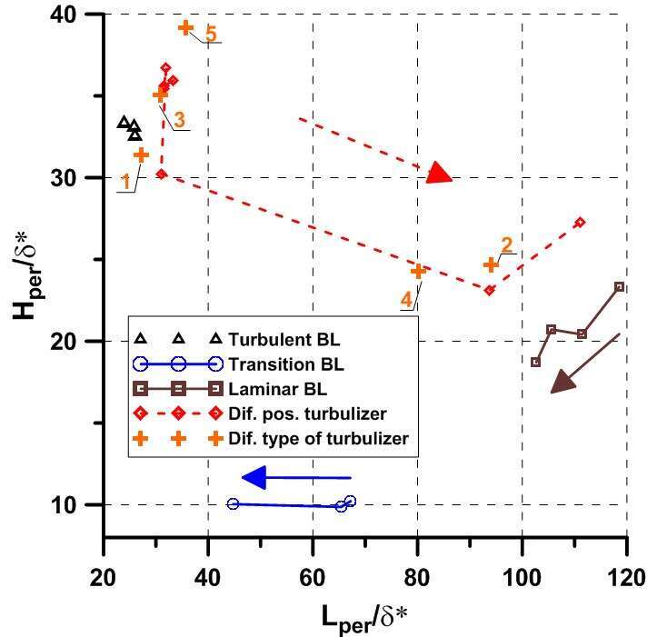
Fig. 3 Dimensionless parameters of SWBLI
From Figure 3 it can be seen that the minimum length of the interaction zone corresponds to the turbulent flow, but at the same time Hper is big in this case. For the laminar case Hper/δ* reduces, but Lper/δ* significantly increases. It is necessary to note that increase of pressure for laminar case is not so significant as for the turbulent one. In transitional case there is a very small height of the zone of interaction and much smaller Lper/δ* in comparison to laminar case but a little bigger than in the turbulent case. For laminar and transitional case increasing of Reynolds number (shown by arrow) results in decrease of Hper/δ* and Lper/δ*.
Comparison of the steady parameters of laminar and turbulent SWBLI did not demonstrate significant advantage of one of the interaction. But significantly higher level of pulsations for the laminar interaction leads to greater drag in the wake. Therefore the optimum is to provide SWBLI in the area of laminar-turbulent transition. In addition in this study some optimal types of roughness and their location for reducing effects of SWBLI at inflow laminar BL have been found.
Acknowledgments
The work was supported by EU in framework of FP7 TFAST project, the Mega-grant of the Russian Federation Government to support scientific research under the supervision of leading scientist at Novosibirsk State University, No. 14.Z50.31.0019.
References
1. E.Allison, I.Kroo, P.Sturdza, Y.Suzuki, H.Martins-Rivas. Aircraft Conceptual Design with Natural Laminar Flow // 27th International Congress of The Aeronautical Sciences. 2010.
2. M.Swoboda and W.Nitschef. SWBLI on Transonic Airfoils for Laminar and Turbulent Flow // Journal of aircraft. 1996. Vol.33. No.1. P.100-108.
