The flow resulting from the diffraction of a planar shock over a square cavity installed in a duct was studied experimentally and numerically in [1]. Later, a similar geometry was studied in [2]; in that case the square cavity contained small dust particles and the study was numerical. The present paper is a further step in this topic; it investigates numerically the case when an incident shock wave propagates in a duct, shown in Fig. 1; black square points indicate the locations where pressure history was computed. In the present case the square cavity was filled with either, helium, argon, air or SF6 while the rest of the duct contained only air.
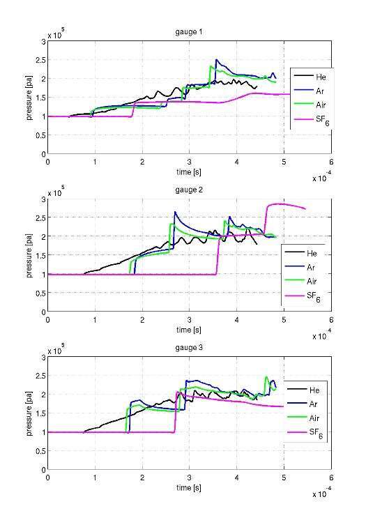
In Fig. 2 pressure histories computed at locations #1, #2 and #3 marked in Fig. 1 are shown for the four different gases inside the square cavity, for an indecent shock of Mach number 1.3. The following features are visible in Fig. 2.
The acoustic impedance and density of the gas inside the square cavity has a pronounced effect on the shape and strength of the diffracting shock wave. In the case of a light gas (He) the diffracting shock wave is reduced to a compression wave. Argon and air have acoustic impedance of similar magnitude and there is only a 10% difference in their ambient speed of sound, therefore similar shock diffraction is evident in these cases. SF6 is significantly heavier than the other three gases and it has the lowest specific heat ratio,γ=1.096, resulting in the strongest pressure jump across the diffracting shock wave. All cases were solved for the same initial conditions, i.e., M=1.3, T0=23.30 C and P0=0.97x10⁵ pascal.
In the pressure histories computed at locations #1 and #2 two shock waves are present. The first is the pressure jump across the diffracted shock over the left wall of the cavity while the second jump is across the reflected shock from the cavity right wall. In the computed pressure history at #3 one sees the pressure jump across the reflected shock from the cavity right wall. When the cavity contains SF6 the shock velocity in the cavity is significantly lower and as a result the diffracted and the reflected shock waves reached locations #1, #2 and #3 later than shock propagating in the other gases. A detailed dissection of the wave pattern and flow fields resulted while using the 4 different gases is given in the full paper.
Fig 1. Geometry of the duct having a square cavity.
Fig 2. Pressure histories computed at three different locations inside the duct`s cavity.
[1] O. Igra, J. Falcovitz, H. Reichenbach and W. Heilig, "Experimental and Numerical Study of the Interaction Process Between a Planar Shock Wave and a Square Cavity", Journal of Fluid Mechanics , Vol. 313, pp. 105 - 130, 1996.
[2] B. Y. Wang, Q. S. Wu, C. Wang, O. Igra and J. Falcovitz “ Shock Wave Diffraction by a Square Cavity Filled with Dusty Gas”, Shock Waves an International Journal on Shock Waves, Detonations and Explosions, Vol. 11, pp. 7-14, 2001.