The flow control around aerial vehicles by using plasma is one of the concerns of the fluid dynamics flow control community for over a decade. In this sense, the deflection of the trajectory of a supersonic projectile by generating plasma on its surface becomes a very realistic application facing the experimental results got previously and in this paper.
The application aims with guided anti-aerial projectiles launched by a 40-mm gun and designed to increase their precision when faced with increasingly agile aerial vehicles flying up to a few kilometres of altitude. The objective of the proposed concept consists in generating one long or several short plasma discharges so that the asymmetry is large and long enough to cause the deviation of the projectile with respect to its initial trajectory. One way of generating a plasma discharge on the projectile surface consists in producing an electric arc discharge between electrodes embedded in the projectile.
Therefore, a low-voltage electric discharge actuator has been developed in order to satisfy the requirements for a use in atmospheric conditions. The actuator is composed of three parts: a high-voltage low-energy activating system, a low-voltage high-energy plasma generator and a low-voltage supply which is common to the previous two parts. The high-voltage low-energy activating system, called discharge trigger, is connected to an electrode pair and is able to break the electric barrier present between the electrodes. The low-voltage high-energy electric discharge generator, called low-voltage generator, is able to produce an electric discharge by the mean of a capacitor connected to another electrode pair through a current controller and a switch. The current controller allows the electric power and therefore the discharge duration to be perfectly controlled for a given energy. The low-voltage supply charges the capacitors of the discharge trigger and of the low-voltage generator.
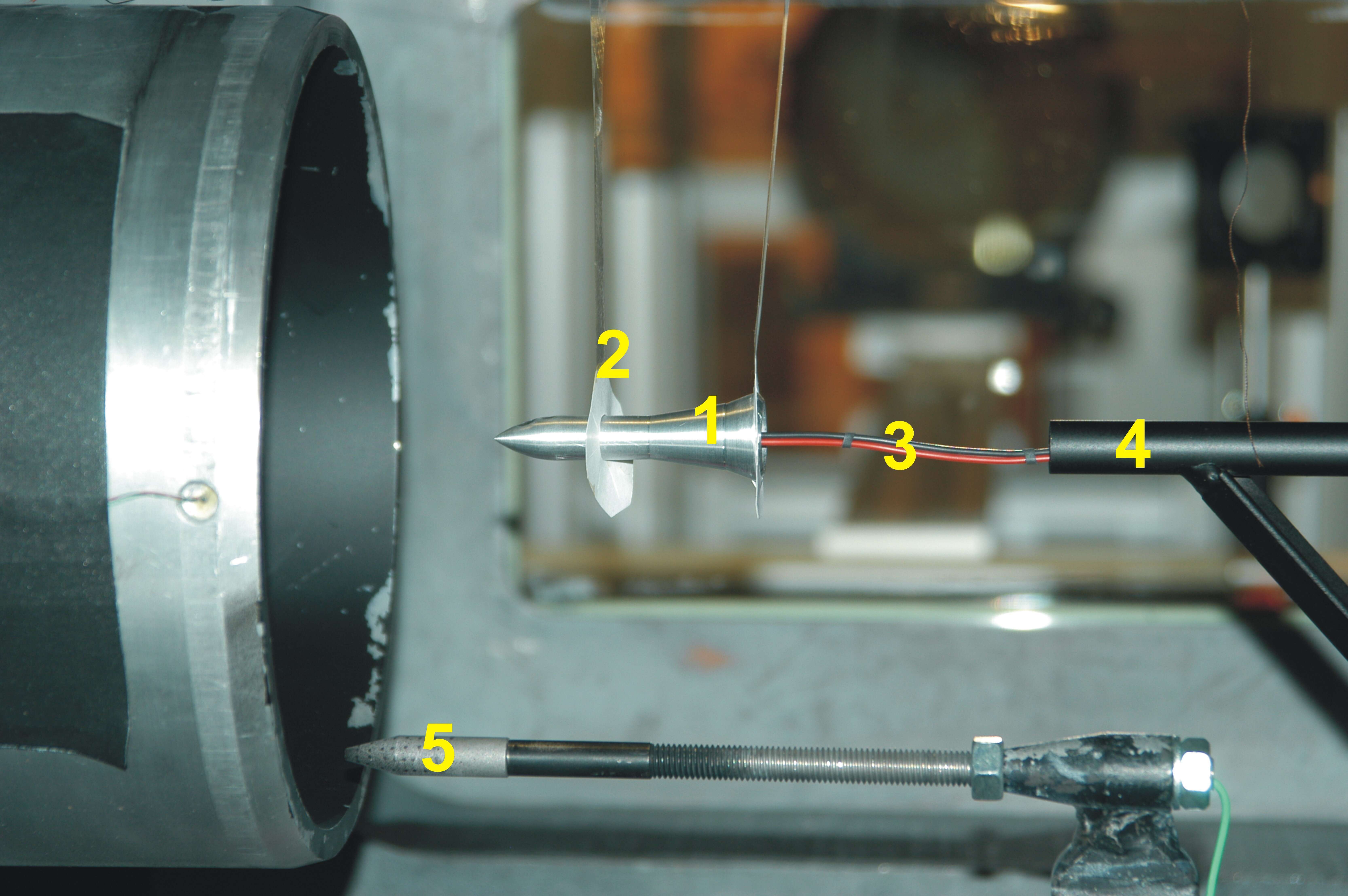
Many experiments have been carried out in the shock-tunnel facility STA of ISL in order to investigate the free-flight motion of a projectile model under realistic conditions. Therefore, the very light Explosively Formed Projectile (EFP) model (1) is hung up inside the test chamber of the shock tunnel in front of the nozzle (Fig: 1).

Fig. 1: EFP model suspended in the test chamber
When the membranes of the shock tunnel burst, the airflow is accelerated up to the desired pressure, temperature and flight velocity, leading to M = 4.5 for the altitude of 2.5 km. The Nylon threads and paper disks (2) constituting the suspension system break and the EPF model (1) can fly freely in the test chamber. Because the main interest lies in the projectile-model behaviour, simple photographs are taken by a Photron-Fastcam CCD camera. This allows the projectile motion to be recorded and analysed at a rate of 10 000 frames per second with an exposure time of 2 µs. Two sets of pictures are taken during each experiment: one picture of the motion in the horizontal plane and one in the vertical plane.
The plasma discharge is produced by using the low-voltage actuator located outside the shock tunnel, due to the dimensions of the actuator and of the projectile model. The electric wires (3) connected to the plasma-discharge actuator are very flexible and they slide through a small tube (4) fixed in the test chamber. The displacement of the model is of the order of the model length. The Pitot-pressure probe (5) allows the determination of the flow conditions.
The experiments consist in generating an electric discharge on the EFP-model ogive when the flow is constant and then analysing the trajectory of the model. Two test results are presented for electric discharges generated by different amounts of stored energy (65 J and 120 J) in the actuator.
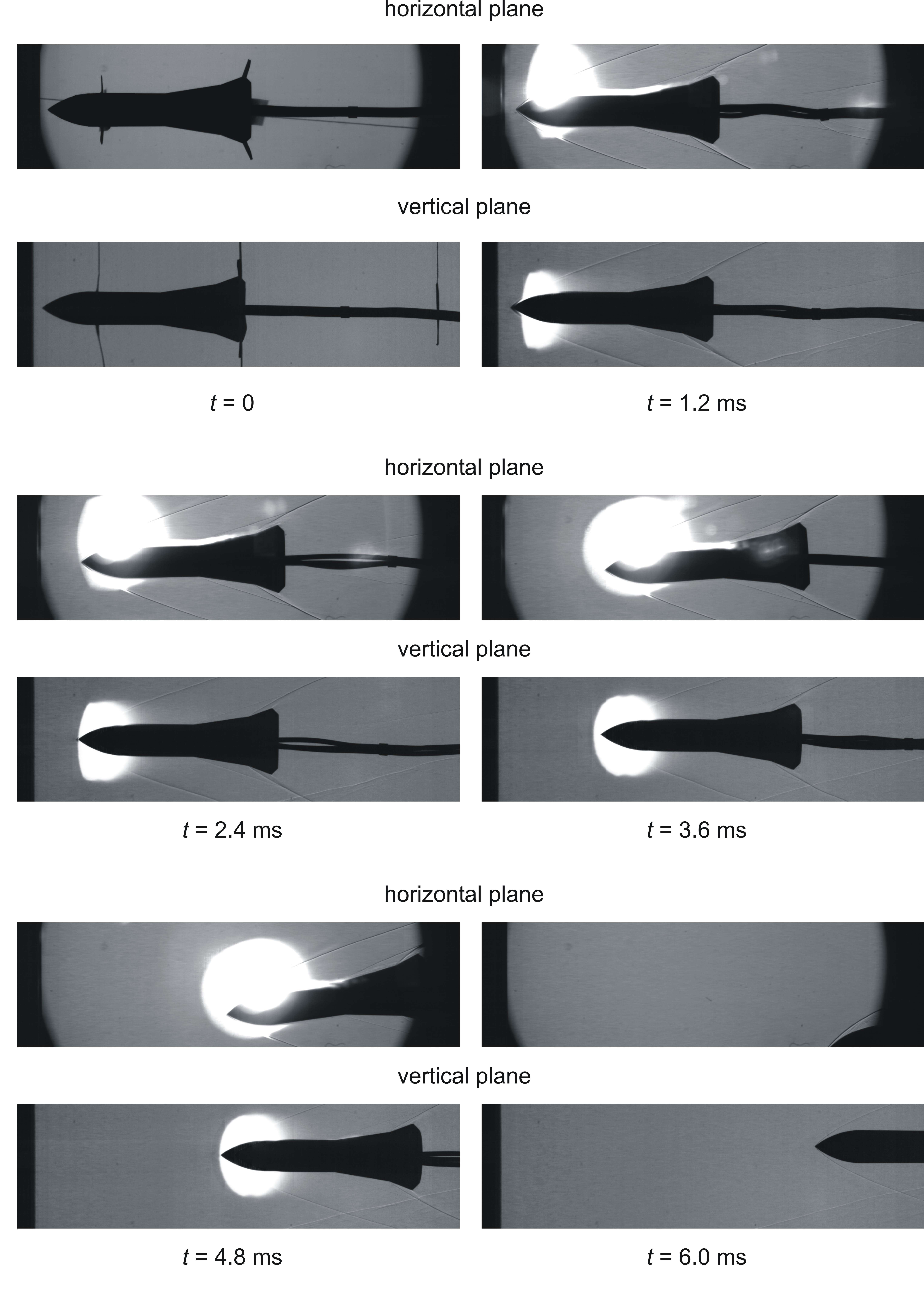
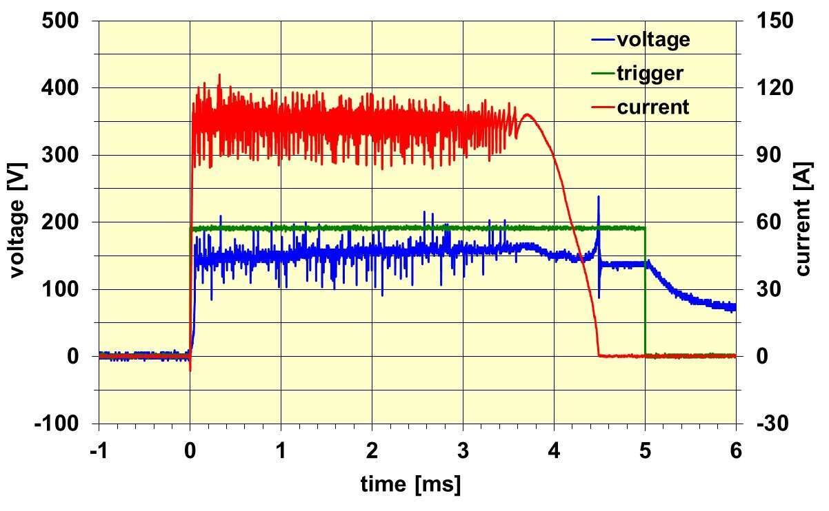
The result in Figure 2 is obtained for the energy of 120 J leading to a plasma duration of 4.5 ms (test 08 09032601). At t = 0 the model is hung up in the test chamber. At t = 1.2 ms, the model slightly moves to the right and the plasma discharge is activated on the ogive. At t = 2.4 ms, the model begins to deviate from its trajectory in the horizontal plane. From t = 2.4 ms to 4.8 ms, the plasma is delivered to the electrodes with a near constant power. In the end (t = 6.0 ms), the plasma is extinguished, the model continues to move in the opposite direction to the plasma, reaching an angle of attack of about -11° and a slight translation is observed in the vertical plane.

Fig. 2: Visualization of the displacement of the free-flight EFP model subjected to a plasma discharge, M = 4.5, E = 120 J (test 08 09032601)
Figure 3 shows the voltage and current measurements recorded during the test demonstrating the correct control of the current delivered to the plasma discharge.

Fig. 3: Voltage and current measurements during the free-flight EFP model subjected to a plasma discharge, M = 4.5, E = 120 J (test 08 09032601)
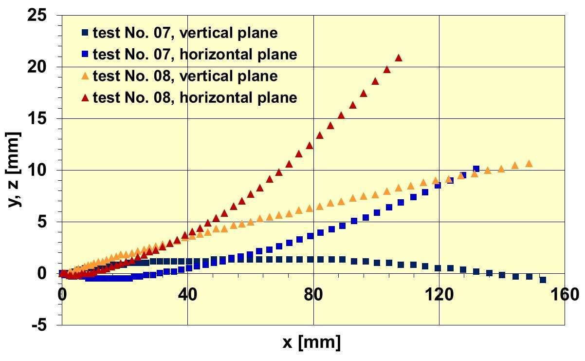
Each picture recorded during the tests is analysed in order to reproduce the displacement of the model tip. Figure 4 shows the displacement in the horizontal and vertical planes for tests 07 (65 J) and 08 (120J). In the case of the test 08, the lateral displacement is 21 mm for a longitudinal displacement of 86 mm.

Fig. 4: Displacement measurement during a plasma discharge, M = 4.5 (tests 07 09032501 and 08 09032601)
The displacement measurement allows the estimation of the resulting side force produced by the plasma discharge. By considering a simple analytical model which relates the model acceleration to its displacement, a resulting side force of around 9 N is obtained by knowing the mass of the model. This first order approach is accurate enough to model the side force and it also can be used for deviation estimations of real projectiles.

