1. Introduction
For a transonic aircraft, one of the major drag sources comes from the aircraft wings. Normal or nearly normal shock waves appear on the upper surface of the wings induce significant stagnation pressure loss across a normal shock which leads to wave drag generation [1]. In order to tackle this problem, various active and passive strategies for achieving shock attenuation have been proposed and tested [2]. Amongst the flow control strategies, the idea of using contour bumps to achieve shock attenuation on transonic aircraft wings is particularly interesting. The operational principle of contour bumps in achieving wave drag reduction is by attenuating the strong normal shock into a series of compression waves or lambda shock structures [1]. Since the strength of the compression waves or the lambda shock is weaker than a single normal shock, across the compression waves or the lambda shock, less stagnation pressure loss appears. This, in turn, generates less wave drag.
Previous studies on contour bumps are mainly focused on optimisation of the bump shapes in order to maximise the effect of wave drag reduction. Only a few studies have been conducted to look at the flow physics of contour bumps in a supersonic free-stream. The experimental study conducted by Bruce and Babinsky [1] is one of the studies which investigated the flow physics of wedge-shaped three-dimensional contour bumps in a Mach 1.3 free-stream. The authors concluded that additional lambda shock structures were formed when the shock impingement location was deviated from the bump crest. These additional lambda shock structures increase the wave drag and causing flow separation downstream of the bump crest. For rounded contour bumps, no detail study has been conducted to investigate their flow physics in the high transonic/low supersonic flow regime. Konig et al. [2] suggested that under the designated conditions, a rounded contour bump performs better in shock attenuation. However, the authors also proposed that the formation of the spanwise vortices at the valley of a round bump indicated that flow separation appeared downstream of the bump crest which increased pressure drag.
The objective of this study is to investigate experimentally the flow physics of a three-dimensional rounded contour bump in a Mach 1.3 freestream. Results obtained from this experimental study could improve our understanding in the flow physics of rounded contour bumps and also be used in optimising contour bump shapes.
2. Experimental Setup
2.1 Trisonic Wind Tunnel
Experiments were conducted in an indraft-type trisonic wind tunnel (Fig. 1). The test section of the wind tunnel has the dimensions of 485.5 mm (length) x 150 mm (width) x 215 mm (height). This wind tunnel is able to provide a stable continuous Mach 1.3 freestream flow for 5 seconds with a variation of flow Mach number (M) of M=1.3±0.01. A movable shock holding plate was suspended from the ceiling of the test section (Fig. 2) to generate a normal shock for impinging the contour bump at different locations.
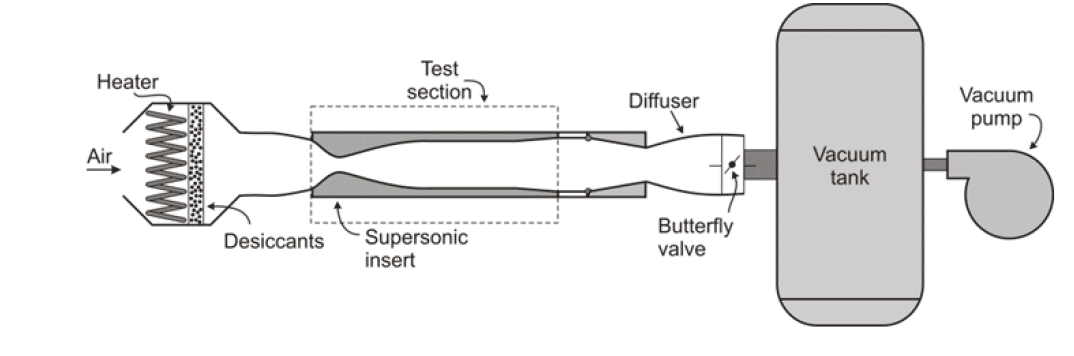
Fig. 1: Schematic of the trisonic wind tunnel.
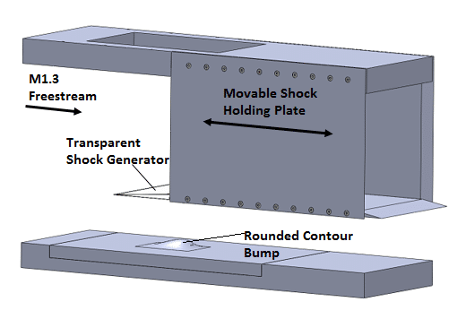
Fig. 2: Schematic of the experimental setup.
2.2 Contour Bump
A three-dimensional rounded contour bump model (Fig. 3) was used in this experimental study. The contour bump has the dimensions of 75 mm (length) x 50 mm (width) x 10 mm (apex height). The model was floor mounted at the wind tunnel test section.
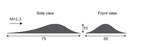
Fig. 3: Schematic of the three-dimensional rounded contour bump.
2.3 Schlieren Photography
A Topler’s z-type Schlieren photography setup was employed. A 450 W continuous Xenon lamp was used to provide illumination and the images were captured by a Photron SA 1.1 high-speed camera. A schematic of the experimental setup is shown in Figure 4.
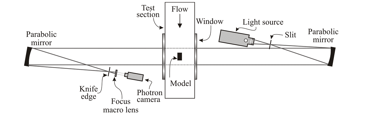
Fig. 4: Schematic setup of the Schlieren photography experiment.
3. Preliminary Results and Discussion
The Schlieren photography image (Fig. 5), captured when the nearly normal shock impinged at the valley of the contour bump is provided as the preliminary result obtained from the experimental study.
From Fig. 5, it can be seen that the normal shock which impinged at the valley of the rounded contour bump was split into two lambda shock structures (F.F.L and S.F.L.). Therefore, it is clear that the rounded contour bump could alter a strong normal shock into a series of weaker lambda shock waves. In additions, from Fig. 5, it can be seen that the front legs (F.F.L. and S.F.L.) of the two lambda shocks were relatively weak in strength. This is believed to be due to the three-dimensional flow relieving effects provided by the round-shaped bump.
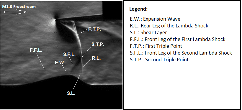
Fig. 5: A nearly normal shock impinging at the valley of a rounded contour bump in a Mach 1.3 freestream.
Moreover, due to the presence of the second lambda shock (S.F.L.) at the bump crest, flow separation appeared immediately downstream of the bump crest. This results in the formation of the shear layer (S.L.) and the highly turbulent flow downstream of the crest of the rounded contour bump.
4. Future Work
Schlieren images obtained at different shock impingement locations on the bump will be shown. In additions, results obtained from surface oil flow visualisation and pressure sensitive paint measurements will be presented in the completed conference paper.
References
[1] Bruce P.J.K. and Babinsky H.: “Experimental Study into the Flow Physics of Three-dimensional Shock Control Bumps”. Journal of Aircraft: devoted to aeronautical science and technology, 2012.
[2] Konig B., Patzold M., Lutz T., Kramer E., Rosemann H., Richter K., and Uhlemann H.: “Numerical and Experimental Validation of Three-dimensional Shock Control Bumps. Journal of Aircraft”, 2009, Vol. 46, No.2, pp. 675-682.
