The free-piston driver [1] offers a safe and efficient means by which to compressively heat a light driver gas, initially at room temperature and at low pressure, to 1000s of Kelvin and 10s of megapascals. This unique capability enables it to drive extremely strong shock waves for impulse facilities, and The University of Queensland (UQ) uses this device to drive its T4, X2, and X3 impulse facilities.
Fundamental to its operation is the passage of the piston down the compression tube. Initially it is accelerated from behind by compressed air, typically reaching maximum speeds of between 100 and 250 m/s. For most of the stroke, the pressure in front of the piston is relatively low, until finally the piston nears the end of the tube. At this point the compression ratio of the driver gas, typically helium, or a mixture of helium and argon, rapidly rises. Eventually the steel diaphragm ruptures, and shock tube flow is initiated.
UQ`s X3 facility is the world`s largest free-piston driven expansion tube. Central to its high performance is its 15m long, 500mm diameter compression tube. Considering one of its higher performance driver operating conditions, the reservoir pressure behind its 200kg piston is initially 9MPa, which corresponds to an initial accelerating force of 1.8MN. When the piston is released, it accelerates forward, and simultaneously an equal and opposite force is applied to the upstream end of the facility. This force reduces as the reservoir gas expands behind the accelerating piston. For the same condition, towards the end of its stroke, the diaphragm ruptures at a pressure of approximately 35MPa. Immediately before rupture, the driver gas applies a maximum force of 6.9MN to both the piston and the downstream end of the driver tube.
The simple analysis above demonstrates that the axial loads which arise in a free-piston driver are enormous, and for this reason the majority of such devices are supported on freely moving rollers. Allowing the facility to freely recoil avoids the problem of designing supporting hardware to restrain the device under loading, however it is usually desirable that the test section itself, where the experiment takes place and measurements are made, is fixed relative to the laboratory frame of reference. Free-piston driven facilities at UQ currently are rigidly connected from the driver through to the tube exit; during operation, the recoil has been accommodated by a sliding seal between the tube exit and the test section.
The high axial loads also induce significant stresses in the tube itself. Both the initial recoil, and the peak load at diaphragm rupture, set in place a complex system of stress waves which traverse the length of the facility at the speed of sound of the wall material. In this case, where the material is steel, the sound speed is approximately 5 km/s, which is comparable to the shock tube flow speed for many operating conditions. It was previously shown in [2] that these stress waves induce strong vibrations in the sensitive acceleration tube wall static pressure transducers, which can lead to erroneous static pressure measurements. This is highly problematic, since these measurements are vital to establishing primary shock speed and test flow static pressure - both essential to test flow reconstruction - and [2] addressed this issue by introducing a compliant joint with a sliding seal at the shock tube-to-acceleration tube joint. This managed to significantly reduce transmitted stress waves, and therefore transducer noise, in both the X2 and X3 facilities; however, geometry constraints meant that the X3 solution required preloading of the joint prior to operation, which made its operation more difficult to optimise in practise, as noted in [2].
Another feature of the above arrangement is that the net vacuum force across the tube exit plane must be reacted at the test section. In recent years, UQ has been developing large diameter nozzles for X3, to enable testing of larger models. Considering a Mach 12 nozzle currently under development, the exit diameter is 660mm, compared to a 270mm inlet external diameter; the corresponding axial vacuum force which would arise is 29kN, which must be resisted through the test section supports. For large diameter nozzles, it would be preferable if this vacuum force could be reacted directly between the nozzle and test section, for example, through a shoulder flange on the nozzle.
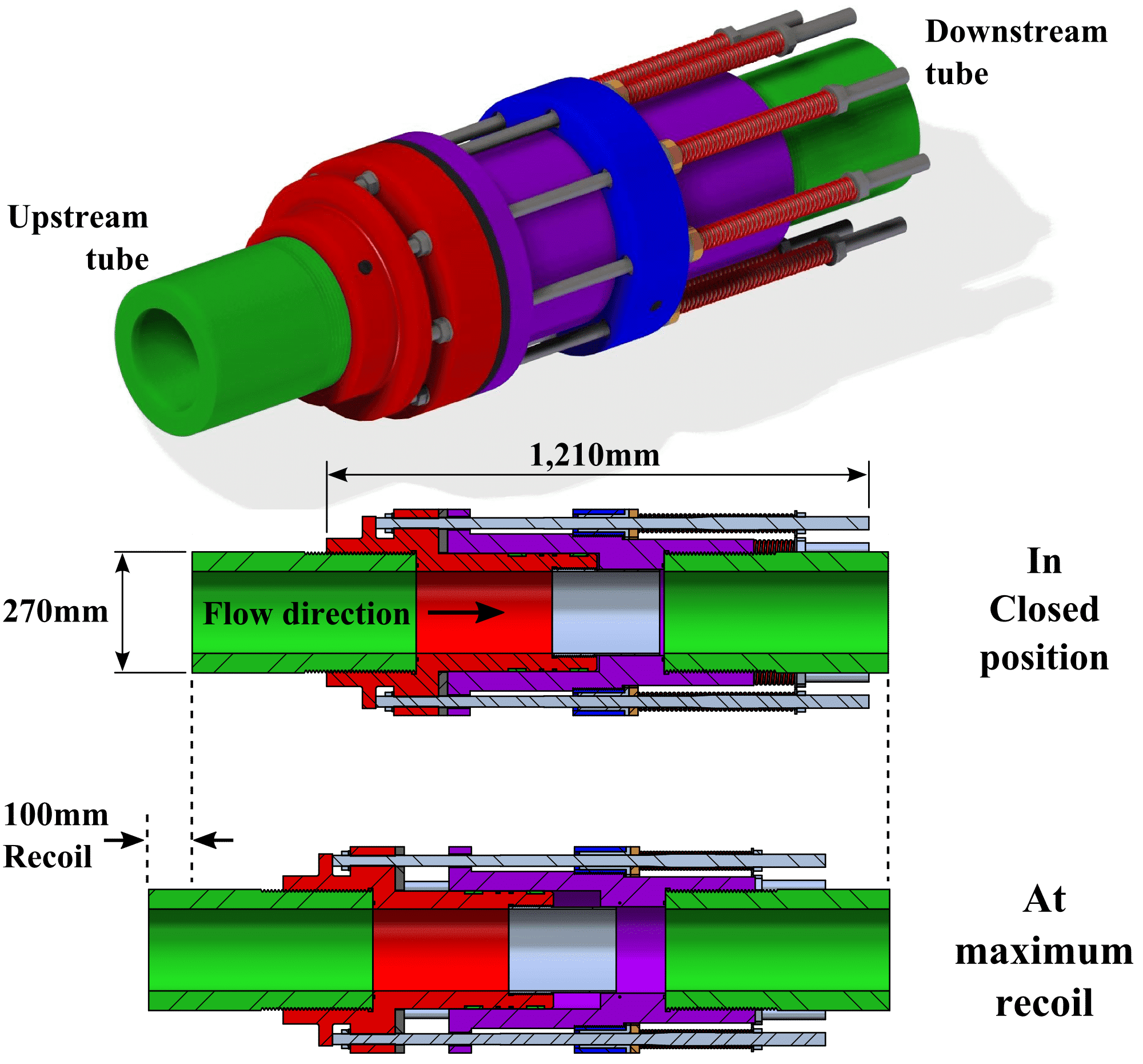
In order to more effectively address the stress wave disturbance issue, and to permit a rigid connection between the nozzle exit and test section, a new sliding joint has been developed to accommodate facility recoil during operation. The joint is shown in Figure 1, and is located at the beginning of the acceleration tube.

Figure 1: New X3 recoil joint.
Eight preloaded springs initially keep the joint closed. When the facility is fired, the upstream tube section recoils, and the sliding joint opens up, as shown in the figure. For X3 operating with its 200kg piston, this recoil is approximately 60mm. The springs are designed so that this recoil displacement induces an increase in axial load of only approximately 2500N, which is negligible in comparison to the axial force associated with displacing the entire downstream acceleration tube (the case when the tube is rigidly joined at this juncture). More importantly, when the piston completes its stroke and the diaphragm ruptures, and axial loading is a maximum, the joint is fully open. The primary mechanism for transmission of stress waves is thus eliminated, and it is expected that stress wave disturbances through the acceleration tube will be effectively eliminated.
Manufacture has recently been completed, and the device will be commissioned in late 2014. This paper will report on results for the new design, including both its mechanical operation, and also its effect on stress wave disturbances in the acceleration tube.
[1] Stalker, R. (1960): Isentropic Compression of Shock Tube Driver Gas. ARS Journal, 30, June, p. 564.
[2] Gildfind, D.E., Jacobs, P.A., Morgan, R.G. (2013): Vibration Isolation in a Free-Piston Driven Expansion Tube Facility. Shock Waves, 23:5, pp. 431–438.

