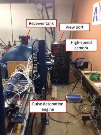
A pulse detonation engine (PDE) typically consists of a straight tube through which a gaseous reactant mixture is detonated from a closed end and from which exhaust products exit from the open end. The detonations occur repetitively. A facility consisting of a PDE attached to a receiver tank is shown in Fig. 1. This PDE has a 50.1 mm bore and is approximately 2 m long. It operates on oxygen and hydrogen at a frequency of up to 10 Hz. To improve the understanding of how a PDE operates, a series of high-speed flow visualization experiments were conducted and reported here. For the experiments, trace amounts of TiO2 were coated onto the inside of the PDE tube
Fig. 1. Facility
The visualizations utilize luminosity from Mie scattering from the TiO2 particles illuminated by the glow from the oxyhydrogen flame. The scattered light is imaged by a Shimadzu HPV-X camera capable of imaging at up to 10 million frames/s at a maximum resolution of 400 x 250 pixels.
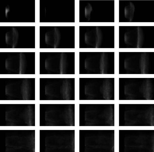
Fig. 2. Side view at 500,000 fps, 1 $\mu$s exposure. Frames shown at 10 μs intervals, left to right and top to bottom.
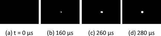
Fig. 3. End view showing flame initiation and propagation at 100,000 fps, 5 μs exposure. Time in the caption is from first visible indication of ignition.
The videos reveal an extremely faint ignition event shown in Fig. 3(a), becoming clearer 160 μs later. By t = 260 μs, the flame is much clearer showing the igniter mounted clearly on the right. The flame develops rapidly and fills the entire tube as shown in the next frame, 20 μs later.
Figure 3 shows a sequence of frames at 10 $\mu$s intervals of the jet exiting the detonation tube. The first frame is at t = 900 μs which is the time for the flame to travel through the tube from ignition. The "starting vortex" similar to that seen in shock tube experiments [1] is seen to radiate from the tube and eventually impinges the receiver tank. Some of the structural details of this vortex can be related to features seen in Fig. 2, such as radial instability waves, which are also visible in the discharge of a shock wave from a tube [2]. A striking feature in the sequence of frames is the glow from the flame which continues until the end of the camera run (t = 2,200 μs).
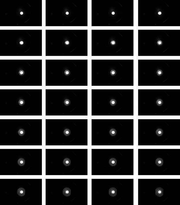
Fig. 4 End view at 100,000 fps, 5 μs exposure, t = [900, 1150; 10 μs.
Acknowledgements
Support for the work by GE Power and Water and by the U.S. Department of Energy is gratefully acknowledged. The authors also acknowledge the support of the UTA Shimadzu Institute for Research Technologies for the use of the high-speed camera.
References
1. Arakeri JH, Das D, Krothapalli A, Lourenco L (2004) Vortex ring formation at the open end of a shock tube: a particle image velocimetry study. Phys Fluids 16(4):1008--1019
2. Maeno K, Kaneta T, Morioka T, Honma H (2005) Pseudo-schlieren CT measurement of three-dimensional flow phenomena on shock waves and vortices discharged from open ends. Shock Waves 14(4):239--249