Shock wave attenuation at microscales has been shown to occur due to the effects of viscosity and heat transfer. Brouillete [1] attempted to quantify these effects in terms of a characteristic Reynolds number and a length scale. Zeitoun & Burtschell [2] simulated micro shock tube flows using unsteady two-dimensional Navier-Stokes equations combined with boundary slip velocities and temperature jump conditions, and showed that reduction in initial pressure or smaller tube diameter increases shock attenuation. Zeitoun et al. [3] showed that investigation of shock wave propagation using Navier-Stokes equations with velocity slip and temperature jump boundary conditions up to a Kundsen number of 0.5 gives results comparable to two kinetic approaches, Direct Simulation Monte Carlo (DSMC) method for Boltzmann equation and numerical solution of BGK equation. Shoev et al. [4] showed that a shock accelerates when it enters a microchannel from a large channel but attenuates during propagation in the microchannel. They used both continuum (Navier-Stokes equations) and kinetic (DSMC method) approaches for Knudsen numbers up to 0.08.Mirshekari and Brouillete [5] designed and fabricated rectangular channel with hydraulic diameter 34 µm and a length of 2000 µm, instrumented with pressure sensors. Mirshekari et al. [6] showed that experimental results on the same microchannel were in agreement with Navier-Stokes computations with no-slip and isothermal boundary condition and a simple shock tube laminar boundary layer model. Arun and Kim [7] investigated rarefaction effects on shock propagation in a micro shock tube using slip boundary conditions. It was shown that slip boundary conditions reduces shock attenuation as compared to no-slip.
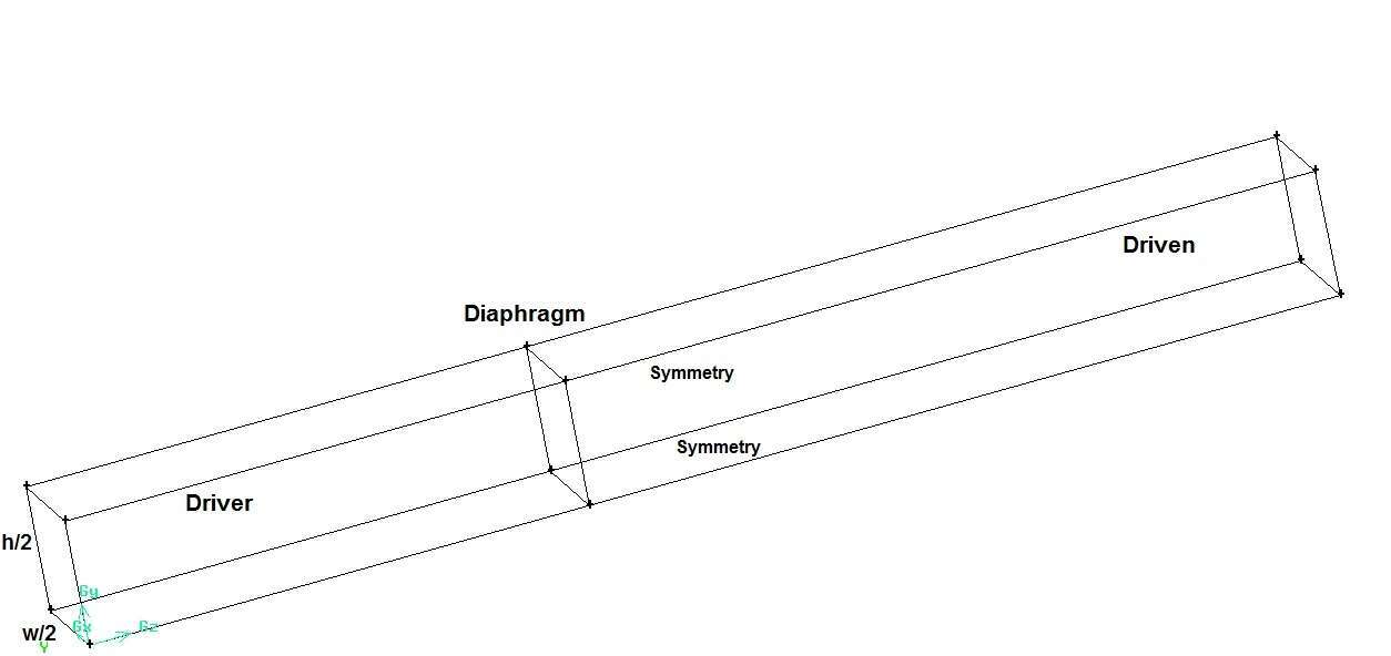
We observe that the need for three-dimensional simulations of shock propagation at microscales was pointed out by many researchers. In the present work, we perform numerical analysis of shock propagation in a micro duct in the configuration of a shock tube, using three-dimensional Navier-Stokes equations at relatively high Knudsen numbers. The simulations are performed for a micro duct of hydraulic diameter 0.2 mm and aspect ratio of 4 with four different initial driven section pressures of 104 Pa, 5 x 10³ Pa, 103 Pa and 5 x 10² Pa. The Knudsen number is in the range 0.0027 to 0.054. Additionally the effect of the shock Mach number is investigated using two different diaphragm pressure ratios so as to generate shocks of Mach numbers 2 and 2.5, when calculated using the inviscid theory. Invoking the symmetry of micro duct, only one fourth of the microchannel is simulated (Fig.1). A no-slip boundary condition is employed at the walls. The commercial code Fluent [8] is used for the analysis.

Fig. 1 Schematic diagram of the micro ductused for the present simulation
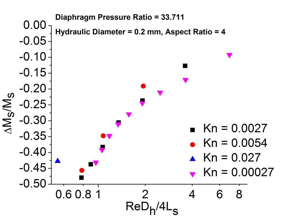
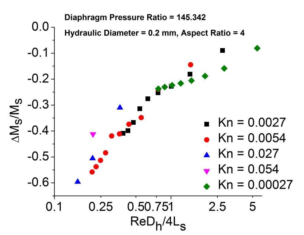
The primary dimensionless parameter is given by ReDh/4Ls, where Dh is the hydraulic diameter of the channel and Ls is taken to be the distance travelled by the shock, following the removal of the diaphragm at t = 0. The shock attenuation is expressed in terms of the change in the shock Mach number (ΔMs) normalized by the ideal shock Mach number (Ms) given by the inviscid theory. This is denoted by ΔMs/Ms, where ΔMs = Ms,actual - Ms.
Some representative results from the simulations are shown in Figures 2 and 3. Rarefaction effects are seen to be significant as the shock Mach number quickly becomes less than unity. The attenuation data for an initial driven section pressure of 105 Pa (Kn = 0.00027) have also been added to highlight the rarefaction effects. It is observed that for the same value of ReDh/4Ls if initial pressure is lowered, i.e., Knudsen number is increased, the attenuation appears to be less. As the initial pressure in the driven section is decreased while maintaining the same diaphragm ratio, the Reynolds number is reduced through the reduction of density in the driven section. Therefore, to achieve a certain value of ReDh/4Ls, the shock travel is less. Additionally, since the shock speed is identical even as the initial driven section pressure decreases, the time taken for the shock travel is less. This implies thinnerboundary layers in the post-shock region and hence less attenuation.

Fig.2 Effect of Knudsen number on Shock attenuation for diaphragm Pressure Ratio = 33.711

Fig.3 Effect of Knudsen number on Shock attenuation for diaphragm Pressure Ratio = 145.342
References
- Brouillette, M.: Shockwaves at microscales. Shock Waves 13, 3-12 (2003)
- Zeitoun, D.E., Burtschell, Y.: Navier–Stokes computations in micro shock tubes. Shock Waves 15, 241-246(2006)
- Zeitoun, D.E., Burtschell, Y., Graur, I.A., Ivanov, M.S., Kudryavtsev, A.N., Bondar Y.A.: Numerical simulation of shock wave propagation in microchannels using continuum and kinetic approaches. Shock Waves 19, 307-316 (2009)
- Shoev, G.V., Bondar, Ye.A.,Khotyanovsky, D.V., Kudryavtsev, A.N., Maruta, K., Ivanov M.S.: Numerical study of the shock wave entry and propagation in a microchannel. Thermophysics and Aeromechanics 19(1), 17-32(2012)
- Mirshekari G., Brouillette M. :Microscale Shock Tube, Microelectromechanical Systems 21(3), 739-748(2012)
- Mirshekari, G., Brouillette M., Giordano J., Hébert C., Parisse J.D., Perrier P.: Shock waves in microchannels. Journal of Fluid Mechanics 724, 259-283 (2013)
- Arun Kumar R. and Heuy Dong Kim.: Computational study of the unsteady flow characteristics of a micro shock tube. Journal of Mechanical Science and Technology 27(2), 451-459 (2013)
- Ansys Fluent 15.0 User’s Guide (2013)

