An isolator module is a constant or nearly constant area duct located between the inlet and combustor of scramjet [1-2]. Its role is to house shock train induced by heat release in a combustor and extend engine operation conditions such as higher equivalence ratio without incurring spillage or unstart [3]. In engine design, the isolator length has to be optimal to minimize the weight and drag of the overall system and fully hold shock train, and therefore it is vital to well understand shock train behavior and accurately calculate shock train length in the isolator under flight conditions. To resolve these issues, numerous investigations [4-13] have performed to examine the influence of parameters such as the entrance conditions, the exit back pressure ratio and geometric effects. It is found that the occurrence of shock train strongly depends on the upstream Mach number and the boundary layer thickness. It is revealed that for a given entrance condition, shock train length increases with an increase of the exit back pressure, and pressure profiles inside shock train present a similarity. Based on the experimental data measured from cylindrical ducts, Waltrup and Billig [5] developed an empirical relationship, which correlates shock train length (s) with Mach number (Ma1), back pressure ratio (Pb/P1), boundary-layer momentum thickness (θ), Reynolds number (Reθ) and duct diameter (D). For a given back pressure ratio, shock train length varies inversely with (Ma12-l)Reθ1/4 and directly with (Dθ)1/2. For a given upstream flow properties, shock train length is a quadratic function of Pb/P1. A further study by Bement et al. [11] confirmed that the Waltrup and Billig correlation is also applicable to calculate shock train length in a rectangular isolator by replacing cylinder diameter with duct height of rectangular section, but a discrepancy exist between the predicted curve and experimental data. The difference should be attributed to geometric difference [12-13].
These fruitful achievements promote a deep understanding of shock train structures and isolator design, but most of results are obtained using room-temperature supply air or cold air as flow gas (Tt=300K), so that the role of air temperature and heat transferred from airflow to the isolator wall cannot be taken into account. At real flight conditions, the air temperature in the isolator is high, and the isolator walls are also subjected to severe aerodynamic heating [14, 15], resulting in the isolator surfaces being heated up. Accordingly, the boundary layer thickness on the wetted surfaces increases, as well as an increase of the gas static temperature in the boundary layer, reducing the fullness of boundary layer profile and the gas density. Thus an increase of wall temperature will lead to a more likely separation of boundary layer, as Coet and Chanetz [16], Bleilebens and Olivier [17], Olivier and Habermann [18], Reinartz [19] and John et al. [20] discovered. Their work also suggests that the boundary layer separation scale induced by shock wave increases with an increase of wall temperature. From these results, it can be inferred that the ability of isolator holding shock train will go down with an increase of wall temperature. This tendency coincides with the research results of Cuffel [15], Fisher et al. [21-23] and Lin et al. [24, 25], but is contrary to the findings of Fischer and Olivier [26]. Fischer and Olivier [26] believed that the opposite effect should be attributed to the wall being heated up beyond the recovery temperature of the airflow. Furthermore, the boundary-layer profile in the correlation of Waltrup and Billig [5] is denoted by boundary-layer momentum thickness, which indirectly involves the wall temperature influences, but whether it fully covers the wall temperature effects or not still need be checked. As mentioned above, the effects of surface temperature and gas temperature on shock train have not been well elucidated. This paper describes our recent efforts in confirming the effects of surface temperature on shock train and isolator performance by a combination of experimental and numerical tests.
Experiments described here were carried out in a direct-connect test facility, composed of a heater, a 2D nozzle, an isolator and a throttle valve to simulate back pressure rise induced by heat release. In the heater, compressed dry air was heated to the required total temperature (Tt) and total pressure (Pt) by hydrogen combustion and oxygen replenishment. A two dimensional nozzle designed for a Mach number of 2.5 was used in conjunction with a nearly constant-area isolator with a length of 600mm and a cross-section area of 50×70mm2. Isolator walls were uniformly heated by a heated ceramic chip, and wall temperatures of vertical and horizontal sides were almost identical. Wall static pressure taps were located on the centerline of the top, bottom and side wall, respectively.
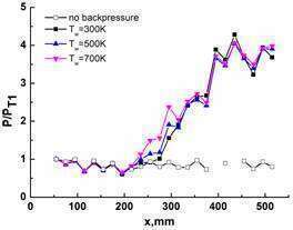
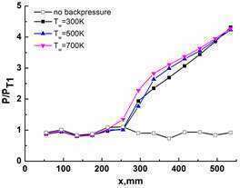
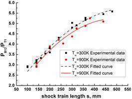
Wall temperature is found to play an important role in the length of shock train. With an increase of wall temperature, shock train length increases, leading to a reduction in the ability of isolator holding shock train, as shown in Fig. 1. This disparity for different back pressure can be more easily observed from experimental statistical results in Fig. 2. Figure 2 shows a series of experimental data distributions on variation of shock train length s with back pressure ratio PB13/PT1 between Tw=300K and Tw=900K. For a constant shock train length, back pressure ratio PB13/PT1 reduces with an increase of wall temperature. The difference in PB13/PT1 between Tw=300K and Tw=900K increases with an increase of shock train length.
a) Top wall b) Bottom wall
Fig. 1 Wall pressure distributions of the rectangular isolator for different wall temperatures at the condition I and PB13/PT1≈4.3 (experiment).
Fig. 2 Statistical analysis on variation of shock train length s with back pressure ratio PB13/PT1 between Tw=300K and Tw=900K at the condition I (experiment).
References
[1] Heiser W H, Pratt D T. Hypersonic Airbreathing Propulsion [M]. Washington D C: AIAA, 1993.
[2] Curran E T, Murthy S N B. Scramjet Propulsion [M]. Washington, D C:AIAA, 2001.
[3] Billig F S, Dugger G L, Waltrup P J. Inlet combustor interface problems in scramjet engines. The First International Symposium on Air Breathing Propulsion, Marseille, France, June 1972.
[4] Mtsuo K, Miyazato Y, Kim H D. Shock train and pseudo-shock phenomena in internal gas flows. Progress in Aerospace Sciences, 1999, 35:33-100.
[5] Waltrup P J, Billig F S. Structure of Shock Waves in Cylindrical Ducts. AIAA Journal, Vol. 11, No. 10, 1973, pp.1404–1408.
[6] Carroll B F, Dutton J C. Characteristics of Multiple Shock-Wave/Turbulent Boundary-Layer Interactions in Rectangular Ducts. Jet of Propulsion, 1990, 6(2):186-193.
[7] Carroll B E, Dutton J C. Turbulence phenomena in a multiple normal shock Wave/turbulent boundary layer interaction. AIAA Journal, 1992, 30(1):43-48.
[8] Matsuo K. Shock train and pseudo-shock phenomena in supersonic internal flows. Journal of Thermal Science, August 2003, Volume 12, Issue 3, pp 204-208.
[9] A. Weiss, A. Grzona, H. Olivier. Behavior of shock trains in a diverging duct. Exp. Fluids (2010) 49:355–365.
[10] Tang H. J., Sun S, Huang H X. Behavior of shock trains in a hypersonic inlet/isolator model with complex background waves. Experiments in Fluids, December 2012, Vol. 53, No. 6, pp.1647-1661.
[11] Bement D A, Stevens J R, Thompson M W. Measured operating characteristics of a rectangular combustor/inlet isolator. AIAA Paper 90-2221, 1990.
[12] Lin P. Geometric effects on pre-combustion shock train in constant area isolators[C]. AIAA 93-1838, 1993.
[13] Cox-Stouffer S K, Hagenmaier M A. The Effect of Aspect Ratio on Isolator Performance. AIAA 2001-0519.
[14] Baker P J. Heat Transfer in a Supersonic Parallel Diffuser [J]. Journal of Mechanical Engineering Science, 1965, 7:1-7.
[15] Cuffel R F, Backf L H. Flow and Heat Transfer Measurements in a Pseudo-Shock Region with Surface Cooling[J]. AIAA Journal, 1976, 14(12):1716-1722.
[16] Coet M C, Chanetz B. Thermal effects in shock wave/boundary layer interactions in hypersonic processes [J]. Recherche Aerospatiale/Aerospace Research, 1994, 4:251-268.
[17] Bleilebens M, Olivier H. On the influence of elevated surface temperatures on hypersonic shock wave/boundary layer interaction at a heated ramp model [J]. Shock Waves, 2006, 15:301–312.
[18] Olivier H, Habermann M. Use of shock tunnels for hypersonic propulsion testing [C]. AIAA Paper 1999-2447.
[19] Reinartz B U. Computation of wall heat fluxes in hypersonic inlet flows [C]. AIAA Paper 2002-0506.
[20] John B, Kulkarni V N, Natarajan G. Shock wave boundary layer interactions in hypersonic flows [J]. International Journal of Heat and Mass Transfer, 2014, 70: 81–90.
[21] Fischer C, Olivier H. Experimental Investigation of the Internal Flow Field of a Scramjet Engine[C]. AIAA 2009-7369, 2009.
[22] Fischer C, Neuenhahn T, Olivier H. Numerical Investigation of the Isolator Flow Field of a SCRAMJET Engine with Elevated Wall Temperatures[J]. New Results in Numerical and Experimental Fluid Mechanics VII, Notes on Numerical Fluid Mechanics and Multidisciplinary Design (NNFM), 2010, 112:415–422.
[23] Fischer C, Olivier H. Experimental Investigation of the Shock Train in an Isolator of a Scramjet Inlet[C]. AIAA 2011-2220, 2011.
[24] Lin K C, Tam C J, Jackson K R, et al. Characterization of Shock Train Structures Inside Constant-Area Isolators of Model Scramjet Combustors [C]. AIAA 2006-0816, 2006.
[25] Lin K C, Tam C J, Eklund D R, et al. Effects of Temperature and Head Transfer on Shock Train Structures Inside Constant-Area Isolators [C]. AIAA 2006-0817, 2006.
[26] Fischer C and Olivier H. Experimental Investigation of Wall and Total Temperature Influence on a Shock Train [J]. AIAA Journal, 2014, 52(4):757-766.