The ability to collect accurate experimental data has allowed designers to gather valuable information in aerodynamics research and to analyse the behaviour of flows subject to varying conditions, often without building full-scale prototypes. To fulfil this need, wind tunnels that provide the working section with uniform, steady, and low-turbulence flow are essential.
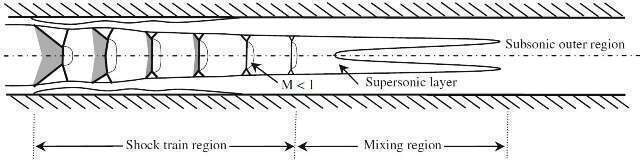
The wind tunnel used for this study was initially intended for a transonic project (Giuni 2010) and has been redesigned to analyse the complex interaction of a shock wave with the boundary layer in internal ducts, known as shock train, schematically shown in Figure 1. The study of the shock wave structure which forms in a nearly constant-area duct is particularly relevant for the prediction and control of a shock interacting with the boundary layer as it finds important application in high-speed flow devices, such as supersonic compressors, ejectors, wind-tunnel diffusers, and ramjets/scramjets inlets. The purpose of the present paper is to examine the flow physics characterising the shock wave structure which forms inside a duct along with the parameters which need to be considered in the design of an indraft supersonic wind tunnel.
Figure 1: Sketch of a shock train structure (Weiss et al. (Weiss 2010))
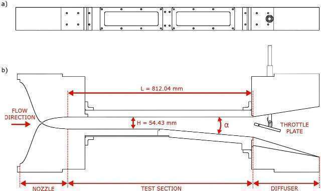
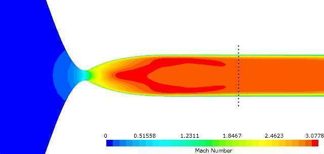
As shown in Figure 2, the air travels from the left to the right, entering the inlet at atmospheric pressure and discharging into a vacuum tank of 34000m3 volume pumped down to a pressure of approximately 0.001bar. Different flow conditions are obtained in the test section by varying the nozzle contour for Mach 2, 3, and 4, designed with the method of characteristics. This numerical procedure assumes the flow reversible and adiabatic since the dissipative frictional and viscous effects are neglected. Methods for taking into account the boundary-layer effect consist in correcting the nozzle contour at each point by an amount equal to the local boundary-layer thickness (Butler 2010), but the accuracy is doubtful due to the assumption they rely on (Yu 1958). Therefore, for the current design, the nozzle contours have been validated by numerical simulation on STAR-CCM+, as the Mach 3 nozzle shows in Figure 3.
Figure 2: Schematics of the wind tunnel: a) Top view; b) Side view
Figure 3: Simulated Mach 3.0 flow
The mechanism of deceleration of a supersonic flow to subsonic velocity inside a constant-area duct, takes place through the formation of a normal shock at a certain position in the flow passage with low Mach numbers and a small influence of the boundary layer (Squire 1996). As the flow Mach number increases, the effect of increased blockage due to the boundary-layer growing becomes more relevant with promotion of multiple shock interactions and increment of the length of the wave structure (Om 1985).
In air-breathing engines, a constant-area duct, called isolator, is placed before the combustion chamber with the purpose to separate and protect the inlet flow from the adverse pressure rise due to the combustion. The flow pattern which is generated inside the isolator dictates the length of the duct since it must be sufficient to prevent inlet unstart, but not overly long to avoid additional shear losses (Billig 1990).
The particular flow feature investigated here has required the design of the test section as a narrow duct. According to Ikui et al. (Ikui 1981) the length of the shock train structure, defined as the region from the head of the shock train to the end of the subsequent static pressure recovery region, increases with both the boundary-layer thickness and the Mach number upstream of the shock train.
The optimum length of a constant-area passage has been found between 8 to 12 tube diameters for Mach numbers from 1.8 to 4.2 (Neumann 1950). Also Sullins (Sullins 1992) reported that, with a duct length of 10-20 duct heights, the shock train pressure rise reaches up to 95% of the normal shock strength. Therefore, for this study the duct has been designed with a cross-sectional area of dimensions 101.60mm x 54.42mm (width x height) and 812.04mm long, to guarantee a length-to-height ratio of 15.
The characteristics of the shock train depend both on the passage geometry and flow conditions, such as Mach and Reynolds numbers, boundary-layer thickness, wall friction, and pressure conditions upstream and downstream of the duct (Lustwerk1950). The length of the test section has promoted the choice of two rectangular windows on the top wall, splitting the visual field in two parts to perform pressure and skin friction measurements using PSP and liquid crystals, in addition to PIV. A lateral window of 558.08mm width allows the visualisation of most of the test section through optical diagnostic techniques, such as schlieren photography.
Because the majority of research has focused on constant-area ducts, the effect of the duct geometry is also analysed by varying the divergence angle α between 0° and 10°, by means of replacing blocks.
In order to simulate the pressure variation in the combustion chamber, a quick and accurate choke system allows to adjust the second throat cross-sectional area. With a device similar to that of Ostras & Penzin (Ostras 1975), the current design uses a pivoting flat plate placed in the diffuser.