Impinging shock boundary layer interactions are of particular importance in Scramjet intakes in hypersonic speeds. At off-design (higher than the design) Mach numbers, the ramp shock hits the cowl plate boundary layer; the possible separation of the boundary layer, which occurs near the leading edge, significantly affects the performance of the system [1]. Further, in such a case the separation length is comparable to the distance of shock impingement location from the leading edge, and separation bubbles of such length scales are termed large separation bubbles [2]. At high impinging shock strengths (typical of hypersonic flows) the large separation bubbles near the leading edge are found to follow an inviscid similarity law independent of Reynolds number: the scaled separation length was proportional to the ratio of reattachment pressure to the free stream pressure and inversely proportional to the free stream Mach number. While the similarity law is proposed based on shock tunnel experiments on impinging shock interactions near sharp leading edge, the role of leading edge bluntness on such interactions presents a curious case especially as the flow separation is expectedly near the leading edge. There are very few investigations on the effect of leading edge bluntness on shock boundary layer interactions [3,4] in general; however it is an interesting case when the separation occurs close to the leading edge, which is not systematically studied. It is with this backdrop that shock tunnel experiments complemented by numerical studies are initiated in order to understand hypersonic impinging shock boundary layer interactions near blunt leading edges.
Experiments are performed in IISc hypersonic shock tunnel HST-2 at nominal Mach numbers of 5.67 and 8.52, at total enthalpies of 1.44 MJ/kg to 1.94 MJ/kg and free stream Reynolds number of 6.26e+05 and 2.62e+05 respectively, corresponding to laminar boundary layers. The strong impinging shock is generated by a wedge (shock generator) at angle 30.96 degrees to the free stream; the shock impinges on a flat plate surface, 57 mm below the bottom of the wedge. The wedge and the flat plate are held by a fixture which mounts them inside the tunnel test section. The flat plate can be moved back and forth on the fixture such that the location of shock impingement can be varied. In the present study the plate leading edge is placed at two different downstream distances from the leading edge of the wedge- 15 mm and 30 mm- by which for given Mach number the shock impingement location is varied by a distance of 15 mm. There are different leading edge inserts for the flat plate model; experiments are done with a sharp leading edge, and with blunt leading edges of four different bluntness radii- 2 mm, 4 mm, 6 mm and 8 mm. The flow field is studied by means of (time resolved) schlieren flow visualizations using a high speed camera (operated at 10,000 frames per second) and surface pressure measurements on the plate using fast response PCB pressure sensors (natural frequency of 500 KHz). A comparison of schlieren images between the case of sharp leading edge and (4 mm) blunt leading edge (30 mm behind the leading edge of the wedge) at Mach 5.67 is shown in Fig. 1. The various features of the interaction are indicated. The corresponding surface pressure distributions for the two cases are compared in Fig. 2. The separation length (approximately the distance between the foot of separation and reattachment shocks) can be estimated from the schlieren images. In both the cases the separation lengths are apparently comparable to the distance of (inviscid) shock impingement from the leading edge. It is also apparent that the separation length is shorter for the blunt leading edge case; the location of separation is very close to the sharp leading edge, while for the blunt leading edge case it is relatively downstream. The peak pressure, close the reattachment location, was measured to be around 4.5e+04 Pascals for sharp leading edge as compared to 2.5e+04 Pascals for 4mm blunt leading edge. The reattachment location at the wall was seen to shift towards the leading edge for blunt case. Investigations on the relation between the separation length, measured pressures, the freestream conditions and the bluntness are underway. The flow field is also numerical simulated using the commercial software CFX v5 so as to complement the experiments in understanding the bluntness effects on shock induced large separation bubbles. Detailed experimental and numerical results and the physics of the interaction in the presence of bluntness shall be presented in the full paper.
![Schlieren images of impinging shock boundary layer interactions: (a) Sharp leading edge [2], (b) 4mm blunt leading edge](http://events.eventact.com/Ortra/16496/ia_full.PNG)
Figure 1 : Schlieren images of impinging shock boundary layer interactions: (a) Sharp leading edge [2], (b) 4mm blunt leading edge
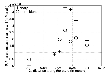
Figure 2 : Comparison of surface pressure distributions between sharp and 4 mm blunt leading edges
References:
1. Mahapatra, D and Jagadeesh, G (2008) “Shock tunnel studies on cowl/ramp shock interactions in a generic scramjet inlet”, In: Proceedings of The Institution of Mechanical Engineers Part G-Journal of Arospace Engineering, 222 (G8). pp. 1183-1191.
2. Sriram R, “Shock tunnel investigations on hypersonic impinging shock wave boundary layer interactions”, PhD Thesis, Department of Aerospace Engineering, Indian Institute of Science, Bangalore, 2013
3. M S Holden and J R Moselle, “Theoretical and Experimental Studies of the Shock Wave-Boundary Layer interaction on compressible surfaces in Hypersonic flow”, ARL Technical Documentary, Cornell Aeronautical Laboratory, Inc. Buffalo, New York.
4. Vinayak Kulkarni and Bibin John, “Effect of leading edge bluntness on the interaction of ramp induced shock wave with laminar boundary layer at hypersonic speed”, 2014 Computers and Fluids, Vol 8, Issue 12
