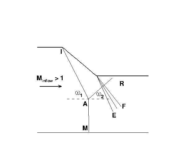
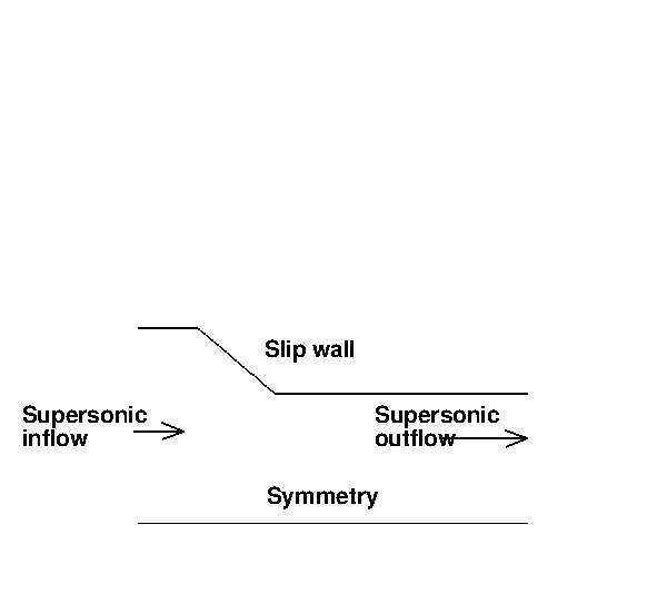
The startup phase of liquid rocket engine nozzles are characterized by the overexpansion of the flow, with internal boundary layer separation and shock formation. This produces dynamic side-loads, which reduce the safe life of the engine and can lead to the failure of the nozzle structure. This is the main reason why the shock and flow structures of highly overexpanded nozzles have been studied for several decades [1–3]. Very recently, the work of Gvozdeva et al. [4] has shown a new configuration of shock reflection in a stationary supersonic gas flow. Figure 1 shows a schematic of a Mach reflection: the oblique shock IA with angle ω1 , the reflected shock AR with angle ω2 , the Mach disk AM and the expansion fan EF. The new three shock configuration is characterized by a negative angle ω2 of the reflected shock, a Mach number greater than 3 and an adiabatic index γ smaller than 1.4. Gvozdeva et al. [4] computed for the first time this particular configuration by means of a Reynolds-Averaged Navier-Stokes equations solver. In their work this shock reflection appears to be unstable. In fact, with a negative reflection angle, the gas would start to accumulate in the center plane. That would lead to choking of the flow and to the upstream movement of the shock system. The possible onset of this configuration is of interest, since in the hot supersonic jet exhausting from a rocket nozzle the Mach number is generally higher than 3 and the adiabatic index less than 1.4. Therefore a negative angle of reflection may occur, with a consequent instability of th flow structure and a consequent negative effect on the performance and structural integrity. In the present work, a numerical campaign is conducted in order to obtain two goals: 1) to verify if the available numerical solver is able to obtain the shock reflection with a negative angle; 2) to investigate if this new shock configuration can occur in an overexpanded nozzle flow. The steady state numerical solutions are carried out by means of an in-house finite volume Reynolds-Averaged Navier-Stokes (RANS) equations solver [5]. The computational domain used to accomplish the first task consists in a 2D planar ramp with an angle of 40◦ , see figure 2. Starting from a steady state solution featuring a Mach disk and a reflected shock with a positive angle, obtained with an inflow Mach number Minflow equal to 3.5 and with γ=1.2, the inflow Mach number is increased until a numerical solution is obtained with a negative angle of reflection ω2 . This solution is obtained with Minflow = 5 and it is reported in figure 4 and 5. These pictures show the pressure field of the whole domain and an enlargement of the triple point. It can be seen that the reflected shock has a small negative angle. This solution appears to be unstable, according to the results of Gvozdeva et al. [4].
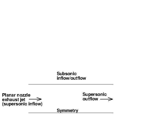
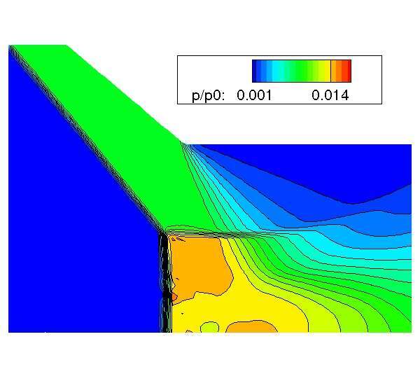
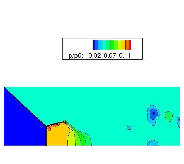
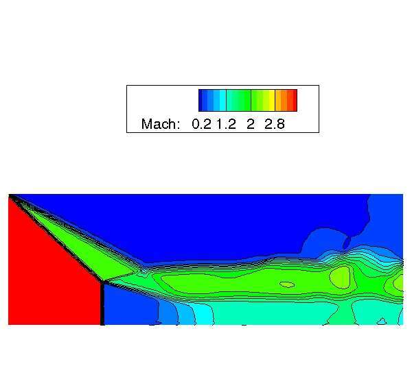
In order to study the shock reflection in an overexpanded 2D planar nozzle exhaust jet, a very simple computational domain is adopted, following the work of Nasuti et al.[6]. This domain consists of a rectangular geometry (see figure 3), where on the left and on the right side a supersonic inlet/outlet is imposed respectively; at the supersonic inlet the flow Mach number Minf low is assigned together with the total pressure p0 and temperature T0 . The bottom side is a symmetry line, while on the upper side a subsonic inflow/outflow is prescribed, according to the sign of the vertical velocity. The preliminary results of this configuration are shown in figures 6 and 7. In figure 6 it is shown the pressure field, while in figure 7 it is shown the Mach number field. The inlet flow parameters are: γ = 1.2, Minflow = 3.5, p0 = 20 bar and pa = 1 bar. From the isentropic relation, given the inflow Mach number of 3.5, the static exhaust jet pressure pe is equal to 0.165 bar, therefore the ratio pa /pe is equal to 6.1. The results shown in figures 6 and 7 present a classical Mach reflection, with a positive angle of the reflected shock.
In the final work the results of a parametric analysis will be shown: the inflow Mach number will beincreased in order to see if it is possible to obtain a negative angle of reflection in an overexpanded jet, and in order to see if this configuration is unstable.
References
1 Nave, L. and Coffey, G., “Sea level side loads in High-Area-Ratio Rocket Engines,” AIAA Paper 73–1284, Nov. 1973, 9th
AIAA/SAE Propulsion Conference.
2 Nasuti, F. and Onofri, M., “Viscous and Inviscid Vortex Generation During Start-up of Rocket Nozzles,” AIAA Journal,
Vol. 36, No. 5, May 1998, pp. 809–815.
3 Kwan, W. and Stark, R., “Flow separation phenomena in subscale rocket nozzles,” 2002.
4 Gvozdeva, L. and Gavrenkov, S., “A New Configuration of Irregular Reflection of Shock Waves,” Jul. 2013, 5th European
Conference for Aeronautics and Space Sciences, Munich, Germany.
5 Betti, B., Martelli, E., Nasuti, F., and Onofri, M., “Numerical Study of Heat Transfer in Film Cooled Thrust Chambers,”
No. 2012-3907, Jul. 2012, 48th AIAA/ASME/SAE/ASEE Joint Propulsion Conference & Exhibit, Atlanta, GE.
6 Nasuti, F. and Onofri, M., “Shock structure in separated nozzle flows,” Shock Waves, Vol. 19, No. 3, 2009, pp. 229–237.