A hypersonic waverider under Mach 7 flow has been analyzed to study the deformation behavior. Waverider (shown in Figure 1) is an aerodynamically derived configuration that rides on the shock waves generated by itself which provides additional compression lift leading to higher lift-to-drag (L/D) ratio. This distinct feature of waverider makes it an attractive candidate for the hypersonic air-breathing cruise mission, which gleans oxygen from atmosphere rather than carrying it on-board. Waverider configuration suffers from extreme thermo-mechanical loading due to skin friction and shock wave.
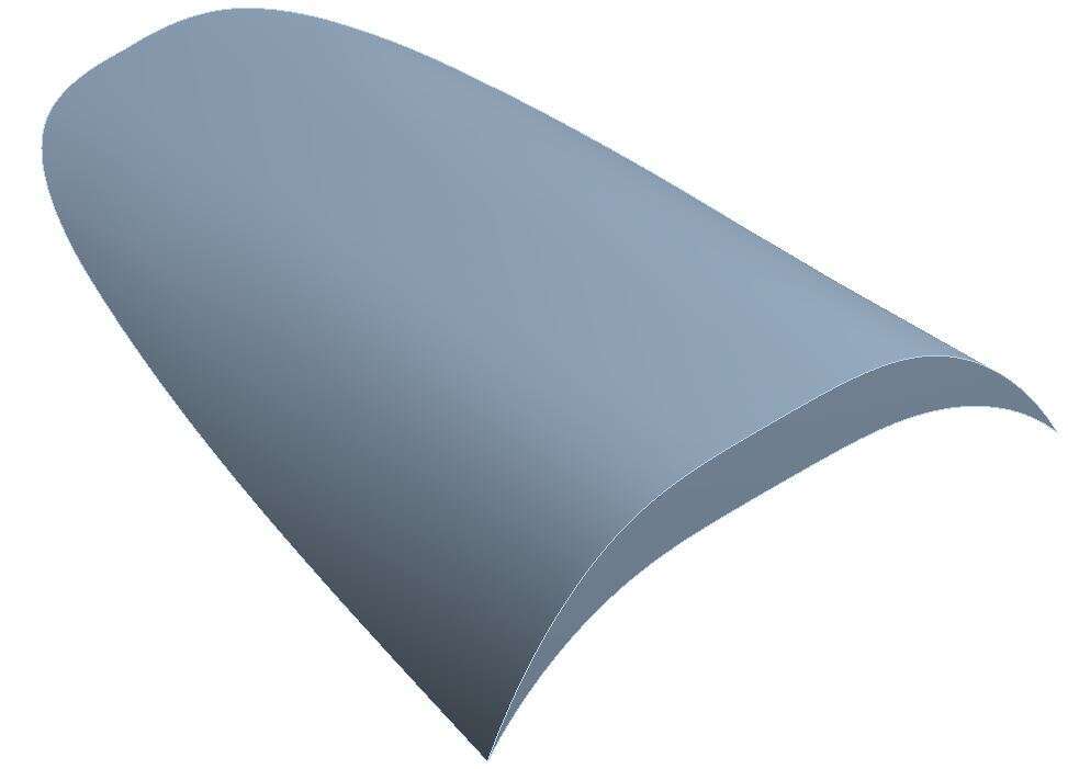
Figure 1 Isometric view of a model hypersonic waverider.
Typically waverider forms the forebody of hypersonic cruise vehicle’s airframe which compress the incoming hypersonic flow through a series of shock to increase the pressure, temperature and reduce the flow velocity which will be ingested into the combustor for adding fuel and generating thrust. Any disturbance in forebody will propagate downstream and affect the scramjet performance. Thus waverider forms critical part of hypersonic cruise system and needs to be analyzed in detail. A wedge based sharp leading edged waverider at zero angle of attack is chosen for study. The structure of waverider is modelled with finite element mesh having 10 node coupled field solid element having translational displacement and temperature degrees of freedom.
Thermal load in terms of convective cold wall heat flux obtained from computational fluid dynamic (CFD) simulation along with initial temperature condition and radiation boundary condition are applied to the structure. The semi-coupled thermo-mechanical analysis is carried by applying the load on finite element model using finite element software package. The nodal temperature at different time instants and pressure load obtained from CFD are mapped on the structure for solving deformation. As the shock wave is attached to the bottom surface of waverider, thermal and pressure load becomes asymmetric with respect to the mid plane of waverider. As a result, the deformation behavior shows bending of waverider with maximum displacement occurring at the leading edge tip as shown in Figure 2. (Shaded area represents the undeformed model)
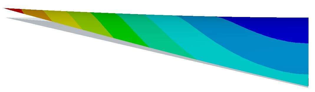
Figure 2 Typical deformation contour of waverider subjected to thermo-mechanical load.
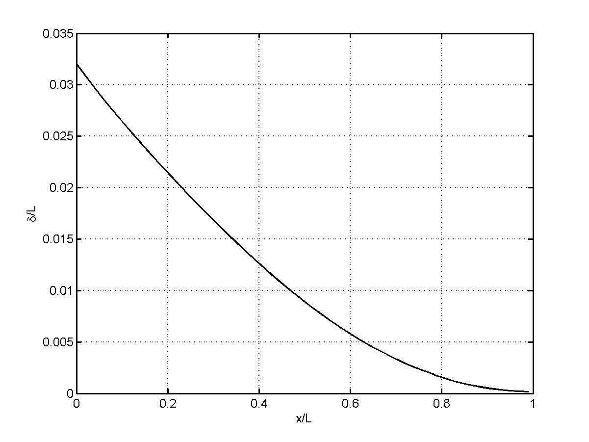
Figure 3 Normalized deformation of waverider along the mid plane.
The above shown Figure 3 gives the normalized deformation along the mid plane of the waverider where L represent the length of the waverider, x represent the distance from the leading edge and δ represent the total deformation. The thermal stress is found to be high all along the leading edge where stagnation occurs (excluding the stress at the constrained location). High stress at the leading edge may also be accounted for the sharp leading edge which acts as stress concentration zone. Results shows that the obtained critical values viz., temperature, deformation, stress are higher than the design allowables under the given condition. The current research aims to address this issue by suitable thermal management in the leading edge of waverider to obtain a robust structure for long endurance hypersonic flight.
Keywords: Hypersonic, Waverider, Finite element method, Coupled thermo structural, Deformation, Stress
References
Anderson, Jr., Hypersonic and High Temperature Gas Dynamics, 2nd edition, AIAA Education Series
Culler A.J and McNamara J.J., “Fluid-Thermal-Structural Modelling and Analysis of Hypersonic Structures under Combined Loading”, 52nd AIAA/ASME/ASCE/AHS/ASC Structures, Structural Dynamics and Materials Conference, 2011
Eckert E.R.G., “Engineering relations for heat transfer and friction in high-velocity laminar and turbulent boundary-layer flow over surfaces with constant pressure and temperature", Trans. ASME 78, 1273-1283, 1956
Rubesin M.W. and Johnson H.A., “A critical review of skin-friction and heat-transfer solutions of the laminar boundary layer of a flat plate", Trans. ASME 71, 383-388, 1949
Van Wie et al., “The hypersonic environment: Required operating conditions and design challenges”, Journal of Materials Science, 915 – 5924, 2004
