Plasmonic and Silicon Nanoparticle Coatings for Thin-Film Photovoltaic Applications
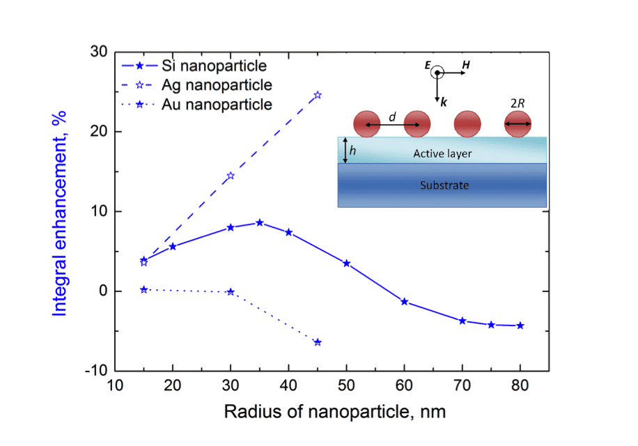
Thin-film solar cells is rapidly growing sector of photovoltaics industry, but the wide range of possible applications is limited by their low efficiency of light absorption in the thin active layer. Plasmonic light trapping coatings were suggested as promising candidate to overcome this problem. Later it has been proposed to implement dielectric and semiconductor nanoparticles with high refractive index for light trapping. In this work we present a comparative analysis of plasmonic and semiconductor light trapping coatings based on periodic arrays of spherical silver, gold, and silicon nanoparticles. We have restricted the parameters of the structure to allow only dipole nanoparticle resonances in the optical range. Our calculations show that silver and silicon coatings demonstrate much higher absorption enhancement comparing to gold coatings. Although, integral enhancement with silicon coating is comparable to silver one, silicon coatings provide an advantage in terms of practical applications, as they are not subjected to aging in comparison to silver coatings. We also dem onstrate that silver and silicon coatings completely suppress reflection at particular frequency because of interaction of electrical and magnetic modes inside the particle, which results in peak-absorbance enhancement in the region between the resonances. This effect is associated with Huygens-like properties of silicon nanoparticles. Moreover, silicon based coatings have narrow banded absorption enhancement in between the magnetic and electric resonances with spectral position strongly dependent on nanoparticle radius. The obtained calculation results show potential applicability of silicon nanocoatings for thin-film photovolatics.

Figure: Integral enhancement for different type of coatings. Inset: 2D periodic array of spherical nanoparticles with radius R on the top of a-Si:H active layer. The active layer (light blue) is on top of the bulk substrate (dark blue). The period of the structure is and the thickness of the active layer is h. The direction of incidence is also shown by the direction of wave vector k.
Powered by Eventact EMS